17 minute read
Fuel System


Points to consider in field on pumps fitted with IKSB
1.It is advised not to attempt to remove the IKSB unit or loosen it for priming purposes under any circumstances. Bleeder screw in the distributor head can be loosened to remove air trapped in FIP.
2.Ensure that 12V is connected to IKSB unit when abnormal smoke is seen in the field during cold operation.
3.When the IKSB unit is energized / de- energized, marginal difference in noise may be observed due to advance in cold and retardation in hot conditions – This is absolutely normal.
4.Do not attempt to handle the pump / lift it holding the IKSB unit.
5.When the vehicle fails to start in cold condition, check if the 12V is connected to IKSB solenoid. Check if battery voltage is 12V.
6.During hand priming using filter ensure that the ignition key is OFF, bleeder screw in filter is loose. DO NOT attempt to prime the system with ignition key ON as it may impart additional resistance to filter hand primer. As a last resort bleeder screw in the pump (center of DV ports) may be opened for priming purposes.
7.In case of suspected problem with the pump, the pump is to be handed over to the authorized BOSCH dealer in undisturbed condition, IKSB should be in undisturbed condition.
8.IKSB unit of one pump should in no circumstance be replaced on another pump without calibration of the pump.
Clutch
1.SERVICING SPECIFICATION
SPECIFICATION (FACTORY)ALLOWABLE LIMIT
A.Clutch disc mainThickness 0.393 in.0.295 in.
B.Pressure plateFlatness0.004 in.0.006 in.
C.Diaphragm springMutual—0.020 in. difference
2.SPECIFICATIONS
1.MakeValeo
2.Type of clutchSingle Plate Diaphragm Spring Dry ceramic pad
3.Main drive member (in)11”
Clearance
1.Release bearing to release finger0.11 inch
2.Release lever height from flywheel (main drive)1.71 ± 0.078 inch
Pedal setting
1.Pedal freeplay1.6 to 1.8 inch
TORQUE
1.Clutch release fork bolt41 - 50 Nm (30 - 37 lb.ft.)
2.Clutch assy. mounting bolt21 - 25 Nm (15 - 18 lb.ft.)
2.REMOVAL & REFITMENT OF CLUTCH FROM TRACTOR REMOVAL

1.Separate front axle with engine from clutch housing.
2.Remove clutch assembly by loosening bolts (A) and separate clutch assembly.
3.Remove main clutch plate (B).
4.Remove PTO clutch damper.
REFITMENT
1.Place a guide shaft tool (C) during assembly of PTO damper.
2.Fit PTO damper (D).
3.Slide the clutch plate (E).
4.Fit the clutch assembly (F) and tighten mounting bolts and remove guide shaft tool (C).
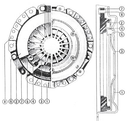
1.Clutch housing5.Pin
2.Pressure plate6.Pivot
3.Diaphragm spring7.Tangential drive strap
4.Ring8. Balance hole
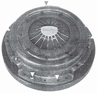
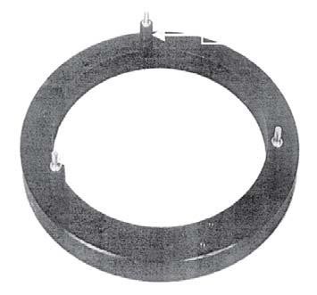
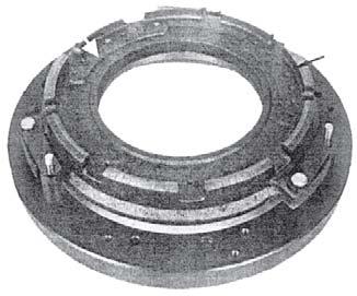
3.SINGLE PLATE DIAPHRAGM CLUTCH
The single plate clutch is a foot operated dry plate type. It consists of a driven plate assembly, cover assembly and a release bearing assembly. The driven plate assembly is clamped between the flywheel rear face and the cover assembly which is bolted to the flywheel. The cover assembly is composed of compress steel cover, a diaphragm, a pressure plate, a belleville washer, return spring and antidrop rivets and clutch assembly mounting bolts with washer. The cover assembly is bolted to the flywheel. The diaphragm is made of spring steel, a flat spring or belleville washer fingers are cut out in the center. When assembled to the cover the diaphragm is pressed to create tension in spring and load the pressure plate.

A tangential drivestrap (7-2) maintain the diaphragm against the fulcrum in the cover (C P type cover). The pressure plate is held against the diaphragm by return spring. The return springs are fasten by rivets (6-2) to the cover and pressure plate. Antidrop rivets are provided to prevent excessive movement of pressure plate.
4.REMOVAL
1.To remove the clutch engine must be separated from the clutch housing. Apply parking hand brake and wedge to rear tire.
2.For spliting the tractor between clutch housing and engine refer the procedure as detailed in “Spliting The Tractor”.
3.Punch the mark matching clutch cover and flywheel position to ensure that the clutch is installed in its original position.
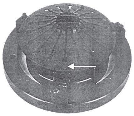
4.Remove the cap screws securing the clutch cover assembly to the flywheel for single plate clutch ref. (fig.1).
5.DISMANTLING
a)Gently pierce out (by drilling) both end of the drive strap rivet and remove pressure plate from the cover assembly.
NOTE: b)Pierce out (by drilling) cover rivets and remove pressure plate sub assembly. c)Then gently pierce out (by drilling) delta rivet riveted head and remove diaphragm.
1.Ensure that the hole on the pressure plate and cover are not damaged.
2.Before doing drilling of operating clamp the job should be hold properly to avoid movement.
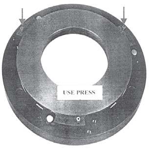
Use service fixture as shown in the figure to do the assembly of pressure plate and drive strap. Use press to rivet the drive strap and pressure plate securely.
1.Before doing drilling operation hold cover assy. properly to avoid movement and also care should be taken to avoid deformation on cover by excess load.
2.During drilling operation the holes on the cover should not get disturbed or enlarged.
3.Fit some of the bolts remove the guide studs if used, fit the remainder of the bolts and tighten them to specified torque.
4.Reverse procedure ‘a to m’.
5.Adjust the clutch linkage.
6.Check power steering reservoir oil level. If fitted. Replacement of facing
Friction facing can be replaced by removing rivets by drilling. Use new set of facing and rivet it with cushion disc by riveting anvil. Ensure that all the rivets are properly riveted : Keep the disc assy. on between centers and check the face out of disc assembly. Face out should be within 1.0 mm.
NOTE:
1.Check for marks or digging of facing rivet on to pressure plate and flywheel face, if so re-machine flywheel face re-machine pressure plate. Machining can be done without dismantling the clutch cover assy. care to be taken to prevent the burrs entering into the assembly.
2.Remove 1.0 mm material from pressure plate face final finishing cut and then verify at H pointing. If all the check points are OK then use cover assy. as it is.
6.CLEANING, INSPECTION & REPAIR a.Wash all parts thoroughly, except the clutch facings, in a cleaning solvent and blow dry with compressed air. b.Inspect the facing of the driven member. If badly glazed, burnt, oil soaked or worn, replacement is necessary. c.Check the hubs of the driven members for excessive wear. Loose rivets, excessive wear at this point is an indication of possible clutch misalignment. Replace, if necessary. d.Inspect the steel discs of the driven members for cracks. If cracked, a new driven member must be installed. Check the vibration dampener springs of the driven members and see if they are loose or broken or have taken a set through heat. If any doubt exists, replace the driven member.
Clutch
e.Inspect the pressure plates for warping or heat cracks. To check the pressure plates, place a straight edge across the pressure plate and if a 0.15mm feeler cab be inserted anywhere between the plate and the straight edge the plate must be replaced.
f.Check the clutch release bearing, sleeve and carrier for wear.
g.Inspect the clutch shafts for wear, try the hubs of the driven members on the shafts and check that, both slide freely but without excessive play. Excessive wear of the clutch shaft splines is an indication of possible clutch misalignment. The clutch shaft should be a snug fit in the clutch shaft pilot bearing. If the bearing is worn, remove it with an extractor and install a new bearing.
h.Inspect the flywheel for signs of scoring. Place a straight edge across the machined face of a flywheel and if a 0.15 mm feeler cab be inserted anywhere between the flywheel face and straight edge in any of the checking positions repairs or replacement is necessary.
i.Machining can be made without disassembling the clutch cover. Care to be taken to prevent the burrs entering into the assembly. Remove 1.0 mm material from pressure plate face and it can be removed in the three phase two rough cut and one final finishing cut and then verify below 4 check points. If all the check points are OK, then use the cover assy. as it is.
NOTE:
1.Too much pedal travel excessively loads the release bearing against thrust spring and reduced travel can result into slippage of clutch plate.
2.Due to wear of lining, pedal play can reduce over a period of time because of lifting up release plate. Re adjustment should be done to avoid excessive wear of release bearing & Date.
7.ASSEMBLY a)Assembly of diaphragm
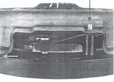
Use service assy. fixture as shown in the figure to assemble diaphragm to cover preferably use the press for riveting.
1.Place the diaphragm over the fixture as shown in the fig.6.
2.Slots in the diaphragm should passes through the delta rivet.

NOTE: Apply high temperature grease over the belleville area of diaphragm spring both side.
3.Place the cover plate to keep it on the diaphragm and tighten the cover plate against outering.

4.There should not be any gap after fully tightening the cover plate.
5.Preferably use press to rivet the delta rivet.
6.Then loosen the mounting bolts and rotate the inner plate and keep the delta rivet for riveting. See fig.7.
The 9 rivets should be assembled on three stages. Then assemble the pressure plate subassembly into cover subassembly by riveting. The stage process are explained below :
1.Place the outer ring properly on the table.
2.Place pressure plate rivet correspondingly as shown in fig.8.
3.Take 4 nos. of drive strap together and insert it to the pressure plate rivet as shown.
4.By using alignment screw, screw it into the ring as shown (Fig.9). This is mainly to avoid dislocation all straps. The above process is for all the 3 locations.
5.Insert pressure plate on to the pressure plate rivet as shown in fig.10.


6.Use hand press to press all the pressure plate rivet.
7.Unscrew the alignment screws and take out pressure plate sub. assy.
NOTE:
1.Drive strap should not rotate freely after riveting.
2.Riveted (formed) head diameter should be 10 to 11 mm.
Clutch
8.Take 3 bushes and fix it on the outer ring fixture.
9.Keep the pressure plate fixture accordingly as shown in fig.11.
10.Take pressure plate sub. assy. and keep it over the fixture as shown fig.12.
11.Ensure that whether the drive straps are properly seated over rivet.
12.Place the cover & diaphragm sub-assy. over the pressure plate sub-assy. Then tighten the cover sub-assy. against the outer ring.
13.Cover the mounting holes locations are marked thus (fig.13).
14.Use press to rivet the cover. Finally loosen the mounting screws and take out clutch assy.
NOTE:
1.There should not be any gap between cover to fixture during assembly.
2.No gap between drive strap and rivet head after riveting.
3.Form riveted head dia 10-11 min.
8.INSTALLATION
a.THE SINGLE PLATE CLUTCH
1.A pilot tool which will slide through the bore of the driven member and locate in the pilot bearing of the flywheel will aid installation of the clutch. NOTE: The end of a transmission shaft will serve for the single clutch, or a special tool is available. See special tool list.
2.Lift the clutch assembly with driven member, and position it on the flywheel dowel with the pilot tool located in the pilot bearing in the flywheel.
3.Align the punch marks on the cover and flywheel then insert and tighten the securing cap screws and lock washers.
NOTE: The clutch securing capscrews should be tighten a turn at a time by diagonal selection til secured to avoid distortion of the cover flange.
4.Withdraw the pilot tool.
5.Installation is now the reversal of the “REMOVAL” procedure.
9.TROUBLE SHOOTING
Troubleprobable Causeremedy
A.Tractor does not move.(1)Engine Clutch Faulty(1) Refer to ‘Engine Clutch’ Section
(2)Transmission Faulty(2)Refer to 'Transmission' Section
(3)Rear Axle Faulty(3)Refer to 'Axles' Section
(4)Differential Faulty(4)Remove Differential, disassemble and inspect
B.Tractor moves but at(1)Engine Clutch Slips(1)Refer to 'Engine Clutch' reduced speed Section
(2)Binding in Transmission(2)Refer to 'Transmission' Section
(3)Binding in Differential(3)Remove, disassemble and inspect.
(4)Binding in Rear Axle(4)Refer to 'Axles' Section
(5)Binding in Front Wheels(5)Refer to 'Wheels' Section
C.Tractor will not turn(1)Steering Mechanism(1)Refer to 'Steering FaultyMechanism' Section
(2)Brake Pedals Interlocked(2)Release Pedal Lock
(3)Differential Faulty(3)Remove, disassemble and inspect
D.Tractor moves but turns(1)Brake Dragging on one(1)Adjust Brakes to one side.side
(2)Front Wheel Faulty(2)Refer to 'Wheels' Section
(3)Steering Mechanism(3)Refer to 'Steering FaultyMechanism' Section
(4)Binding in Differential(4) Remove, Disassemble and inspect
(5)Uneven Tire Inflation(5)Check Tire Pressure Pressure
CHAPTER - 1
2.FLOATS
Sr.Location Size /Min. TorqueMax. Torque No.Description(N-m)(N-m)
1Retainer Main Drive Shaft ToFlange Bolt – M8 x 16L x 1.252125
Clutch Housing
2Upper Cover Clutch HousingFlange Bolt – M8 x 16L x 1.252125
3Clutch Window CoverFlange Bolt – M8 x 16L x 1.252125
4Forward Reverse ShiftingFlange Bolt – M8 x 16L x 1.252125
5Speed 1-2, 3-4 BushFlange Bolt – M8 x 16L x 1.252125
64WD ShiftingFlange Bolt – M8 x 16L x 1.252125
7Retainer Mid - PTO BearingFlange Bolt – M8 x 16L x 1.252125
8Retainer Main Drive Shaft ToFlange Bolt – M8 x 16L x 1.252125
Clutch Housing
9Bearing Retainer Bull ShaftFlange Bolt – M8 x 16L x 1.252125
10Carrier RH To Transmission CaseFlange Bolt – M8 x 16L x 1.252125
11Stopper Wet PTO ClutchFlange Bolt – M8 x 16L x 1.252125
12Upper Cover Transmission CaseFlange Bolt – M10 x 25L4150
13Rear Cover To Transmission CaseFlange Bolt – M10 x 25L4150
14Retainer Rear Axle CarrierM10 x 35L4150
15Carrier Differential Case LH ToBolt M12 x 1.25 x 30L92113 Transmission Case
16Rear Cover To Bearing RetainerBolt M8 x 162125
17Clutch Housing & Transmission CaseFlange Bolt M12 x 40L100124 Interface
18Transmission Case To Mid-PTO HousingFlange Bolt M12 x 35L100124
19Cover Mid-PTO To Transmission CaseFlange Bolt M12 x 35L100124
20Differential Case To Ring GearBolt M10 x 1.25 x 25.66272
21Clutch Housing To Transmission CaseHex. Flange Bolt M14x1.5x40L130150
22Clutch Housing To Transmission CaseStud M14 x 505565
23Clutch Housing To Transmission CaseFlange Nut M14 x 1.5115130
1.Excessive•Transmission fluid insufficient•Replenish Transmission•Improper backlash between differential•Adjust Noisepinion and side gear
•Bearing Worn•Repair
•Wrong grade of oil•Change
•Gear teeth broken/pitted•Replace
•Contaminated Oil•Change
2.Gear slip out of•Shifter fork worn or damaged•Replace mesh•Shifter fork spring weaken or damage•Replace
•Interlock pin fallen•Replace
•Synchronizer unit damaged•Repair or Replace
3.Hard Shifting•Shifter fork worn out or•Replace damaged
•Shifter fork bent•Replace
•Synchronizer unit damaged•Repair or Replace
4.Gears clash•Improper Clutch Setting•Adjust or Repair when shifting•Synchronizer unit defective•Repair or Replace
•Clutch does not release•Adjust
•Wrong grade of oil•Change
5.Differential Lock•Differential lock shifter fork damaged•Replace can not be set•Differential lock shifter fork mounting•Replace spring pin damaged
•Improper movement of differential•Adjust lock shifter fork.
6.Differential Lock•Differential lock shaft spring weaken or•Replace Pedal does notdamaged return•Differential shift/lock ring pin damaged•Replace
FORWARD / REVERSE
Major Components
1.Engine Flywheel
2.Clutch Assembly
A.Transmission Drive Shaft
B.P.T.O. Drive Shaft
C.Speed Driving Shaft
D.Forward - Reverse Synchronizer
E.Forward Gear - Driven
F.Reverse Gear - Driven
Reverse Idler
Transmission Power Flow
Major Components
A.Transmission Drive Shaft
B.PTO Drive Shaft
C.Speed Driving Shaft
D.Forward - Reverse Synchronizer
E.Forward Gear Driven
F.Reverse Gear Driven
G.Forward Gear Driving
H.Reverse Gear Driving
I.Reverse Idler Gear
J.Counter Shaft
Forward Gear Power Flow :
Rotary Power from Transmission Driving Shaft (A) flows to Counter Shaft (J) as per following flow.
Transmission Driving Shaft (A) to Forward Driving Gear (G) to Counter Shaft Forward Gear Driven (E) then to Synchroniser (D) to Counter Shaft (J).
Reverse Gear Power Flow :
Rotary power from Transmission Driving Shaft (A) flows to Counter Shaft (J) as per following flow.
Transmission Driving Shaft (A) to Reverse Driving Gear (H) to Reverse Idler Gear (I) flows to Counter Shaft
Reverse Gear (F) and then to Synchroniser (D) to Counter Shaft (J).
Major components
J.Counter Shaft
C.Speed Driving Shaft
K.Coupling Range & Speed Shaft
L.1st - 2nd Synchronizer
M.1st Gear Driving
N.2nd Gear Driving
O.1st Gear Driven
P.2nd Gear Driven
Q.Range Shaft
The power from Engine via forward and reverse gear rotates the Counter Shaft (J) and 1st - 2nd Synchronizer (L). It equalizes the speed of the involved shafts before the shifting ring engage.
Shifting Ring engaged with 1st Gear
The power flows from Counter Shaft (J) integral gear 1st Gear Driving (M) to 1st Driven Gear (O) on Speed Shaft
(C) to the Synchronizer (L) splined with Speed Shaft. Hence power goes to Range Shaft (Q) through coupling (K).
Shifting Ring engaged with 2nd Gear
The power flows from Counter Shaft (J), 2nd Gear Driving (N) to 2nd Driven Gear (P) on Speed Shaft (C) to the Synchronizer (L) splined with the Speed Shaft. Hence power goes to Range Shaft (Q) through coupling (K).
Speed Gear Section
Major components
J.Counter Shaft
C.Speed Shaft
K.Coupling
R.3rd - 4th Synchronizer
S.3rd Gear Driving
T.4th Gear Driving
U.3rd Gear Driven
V.4th Gear Driven
Q.Range Shaft
Shifter Ring engaged with 3rd gear
The power flows from Counter Shaft (J) 3rd Gear Driving (S) to 3rd Driven Gear (U) on Speed Shaft (C) to the Synchronizer (R) splined with the Speed Shaft. Hence power goes to Range Shaft (Q) through coupling (K).
Shifter ring engaged with 4th gear
The power flows from Counter Shaft (J), 4th Gear Driving (T) to 4th Driven Gear (V) on Speed Shaft (C) to the Synchronizer (R) splined with the Speed Shaft. Hence power goes to Range Shaft (Q) through coupling (K).
Range Gear Section
Major Components
K.Speed Shaft
Q.Range Shaft
A.High Gear Driving
B.High Gear Driven
C.High-Low-Medium Coupling
D.Spline Shaft
E.Coupler
The Range Section arrangement is Constantmesh. The power from Speed Section comes through range shaft through range section. The High and Medium range driving gears are splined to Range Shaft and low gear is integral with the Range Shaft. All range driven gears are free to rotate in the neutral condition on shaft pinion.
Shift Coupling Engaged with high gear
The power from Range Shaft high driving gear (A) flows to high driven gear (B) through coupling (C) to the spline shaft (D) and splined collar.
Range Gear Section
Major Components
K.Speed Shaft
Q.Range Shaft
C.High-Low-Medium Coupling
D.Spline Shaft
E.Coupler
F.Medium Gear Driving
G.Medium Gear Driven
H.Low Gear Driving
I.Low Gear Driven
Shift Coupling Engaged with Medium gear
The power from Range Shaft medium driving gear (F) flows to medium driven gear (G) through Coupling (C) to the spline shaft (D).
Shift Coupling Engaged with Low gear
The power from Range Shaft low driving gear (H) flows to low driven gear (I) through Coupling (C) to the spline shaft (D).
SPEED SECTION A.Dismantling
1.Separate clutch housing from engine (Refer splitting Section).
2.Remove steering, return oil supply to top cover.
3.Remove steering gear and brake linkages as well as shifting linkages and other fitment.
4.Support the clutch housing with suitable arrangement.
5.Remove clutch release bearing (A), shaft (B) and fork (C).
6.Remove front retainer (D).
7.Remove PTO input shaft, remove transmission driving hollow shaft along with front bearing. Hold the gears and spacers in position. Remove gears and spacers.
8.Remove top cover (E) by loosening bolt (F).
9.Remove forward / Reverse and speed shifting arms (G) by removing spring pin (H).
10.Remove forward / Reverse idler shaft positioning bolt (I) and remove idler circlip (J) and assembly by slight tapping.
11Remove forward / Reverse and speed levers (K).
12.Separate forward / Reverse and speed forks removing spring pin (L) by using special tool.
13.Remove speed rail detention bolt, springs and balls, remove forks and rails.
14.Remove middle wall ball bearing by removing circlip top shaft.
15.Remove speed Top Shaft from rear side by removing circlip (M).
16.Push center bearing through rod from rear side.
17.Remove 1 st and 4 th gear bushes.
18.Slide 4 th gear towards front and 1 st gear towards rear.
19.Push top shaft assembly to front or rear.
20.Take out 1 st or 4 th gear.
21.Take out Synchro assembly one by one.
22.Remove rear nut, lock washer, spacer. Remove rear bearing internal circlip and bearing by special tool.
23.Remove front external circlip on counter shaft. Keep it in secured place.
24.Tap the counter shaft slowly, during pushing the countershaft towards rear. Try to rotate countershaft for ease of dismantling. Remove shaft and forward / Reverse gears, Synchro assembly and speed driving gears (3 nos.) and splined bushes.
B.Cleaning and Inspection
1.Lubricate all serviceable bearing and wrap in grease proof paper.
2.Remove all gasket material from joint face.
3.Inspect bushes for wear or damage, worn chipped or broken teeth check splines for correct fit. Check excessive play.
C.Assembly Speed Section
1.Assemble the speed counter shaft in the housing.
2.Fit bearing top shaft.
NOTE:After counter shaft assembly, assemble first, second, third & fourth gears before speed top shaft and idler assembly.
All bearing installation by heating bearing at 80°C to 90°C.
All bearings, bushes, shaft to be lubricated with specified oil for assembling.
3.Assemble the speed top shaft.
4.Assemble shuttle shift assembly in the housing.
5.Insert Speed Top Shaft from rear end, then put bushes, gears and Synchro.
6.Front bearing to be push on Speed Top Shaft and check float as required. To adjust float use graded 1st gear bush.
7.Install front and rear circlip.
8.Assemble shuttle shift fork after counter shaft assembly.
9.Install forward / reverse and speed levers and then arms.
10.Fit the oil seals by using sleeve.
11.Check float.
D.Speed Section - RAIL FITTING
1.Slide rail 3 rd & 4 th from rear side in bottom hole (K).
2.Assemble 3 rd & 4 th fork in rail, keeping synchronizer in neutral and lock rail and fork with roll pin.
3.Drop inter lock pin from top.
4.Slide rail 1 & 2 from rear side in top hole.
5.Assemble 1 & 2 fork keeping synchronizer in neutral and lock fork and rail with roll pin.
6.Insert detent ball, spring, copper washer and retention bolt and torque with specified value.
E.Forward / Reverse Section - RAIL FITTING
1.Insert special tool in clutch housing from inside.
2.Slide rail from front side.
3.Assemble Forward / Reverse fork without ball & spring and assembly tool outside.
4.Align special tool slot and fork hole, then insert ball and spring.
5.Rotate special tool to ensure locking of ball and spring.
6.Slide rail slowly towards rear keeping fork assembly in position with tool.
7.Lock the rail by special bolt and copper washer.
8.Check centralization of fork by dial gauge shifting in forward and reverse direction. If required adjust the centralization putting remaining shims at countershaft rear end bearing. Keeping dummy piece of front retainer.
RANGE SECTION A.Removal
1.Drain oil from Speed and Range section.
2.Split the Tractor between Clutch Housing and Transmission-case as detailed in splitting of tractor.
3.Remove the tires.
4.Remove Hydraulic Lift Housing and Range Section top plate.
NOTE:Place the Transmission-case with axle on suitable stand and suitable support at front before starting work on Range Section.
5.Remove the rear PTO cover assembly along with wet clutch assembly and 540 input shaft and gear assembly.
6.Remove external circlip inside hub and remove hub.
7.Remove PTO middle support bearing rear circlip.
8.Remove PTO intermediate shaft with ball bearing from rear side.
9.Remove spring pin from fork and rail. Remove retainer bolts (2 Nos.), springs & ball and take out the rail & forks.
10.Remove front and rear internal circlip of Range shaft ball bearings.
11.Remove lock nut and lock washer of Range Top Shaft.
12.Slowly tap the Range shaft from rear end. Hold the high and medium gears. After the Range shaft removal, take out the gears.
NOTE:Removal of Spline-shaft refer differential assembly.
D.Rail Fitting – Range Section
1.Slide rail from rear side.
2.Insert fork in coupling and lock with spring pin with rail.
3.Insert ball, spring at front and rear position of transmission-case and insert retention bolt and torque with specified value.
4.Assemble shifter arm in fork slot. Insert cross shaft and lock the arm with roll pin with cross shaft.
4 Wd
A.Theory of Operation
The gear (A) which is mounted on spline shaft constantly mesh with idler gear (B). This gear transmits power to gear 4WD (C) which spins freely on output shaft (D) until engaged by locking collar (E).
When the 4WD lever is pushed down, the locking collar slides so as to engage with gear 4WD (C). Power is then transmitted through the output shaft (D). The propeller shaft is connected to the 4WD axle which give drive to 4WD axle.
B.Dismantling
1.Remove bolt retention for 4WD idler shaft.
2.Take out 4WD idler shaft.
3.Remove 4WD input gear from spline shaft after removing lock nuts.
4.Remove 4WD idler gear, needle bearing and two thrust washers.
5.Remove bolt shaft retention 4WD rail.
6.Tap the rail from rear side and remove from front side of transmission-case.
7.Remove lock plate.
8.Take lever close to wall.
9.Remove fork with ball and spring fitting fork position as per requirement to avoid flying of spring and ball.
10.Remove oil seal and circlip from 4WD output shaft.
11.Tap the output shaft from rear side, take out washer & locking collar.
NOTE:Take care not to fly out the ball and spring when taking out locking collar.
C.Cleaning and Inspection
1.Clean all part with suitable solvent.
2.Check all parts for wear, pitting or any crack.
3.Check the spring tension and tilt or damage.
4.Check backlash of gear, locking collar and output shaft. If it is more than limit, replace it.
D.Assembly
Assemble the removed parts in the reverse sequence of dismantling.


