10 minute read
Hydraulics


B)FUNCTIONING OF DRAFT CONTROL
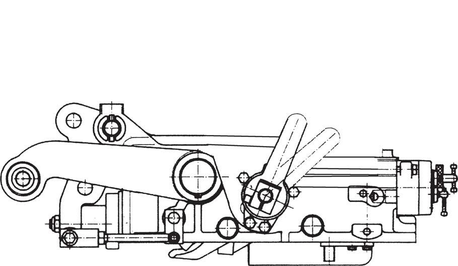
By positioning the control lever (1) for position control against the backstop (E), the crank (4) reaches its maximum position of anti-clockwise rotation. In said position the roller (5) is totally lowered from the inclined plane of position cam (6) allowing the anti- clockwise rotation of flywheel (7) as well as the clockwise rotation of the transmission lever (9) that is pushed by the spring of shaft (21) which in turn will position itself for the discharge position (S). In this way the position levers will not interfere with the functioning of the draft control levers.
By positioning the draft control lever (2) against backstop (F), draft control shaft (16) is caused to rotate clockwise.
The crank (15) being an integral part of shaft (16), will reach its extreme position of clockwise rotation, and by means of tension rod (17) will move roller (11), the latter acting on the draft cam (12). This causes flywheel (7) to rotate clockwise which by means of function shock absorber (8) produces the anti-clockwise rotation of transmission lever (9) thus setting the distributor shaft (21) in delivery position (C) and consequently lifting the arms.
The arms will come to a stop only as soon as the piston comes into contact with the pin of the limit stop (22).
This limit stop, by means of tension rod (23) causes lever (9) to rotate clockwise, thereby compressing the spring of friction shock absorber (8) and thus releasing shaft (21) which now can move to the neutral position (N) where it is pushed outward by its spring.
Moving the draft control lever (2) toward backstop (E), the leverage system will function in the following manner:
The crank (15), being an integral part of the draft shaft (16), rotates counter-clockwise and by means of tension rod (17) causes roller (11) to slide on flywheel (7).
The roller (11), when it meets the inclined plane of the draft cam (12), permits the counterclockwise rotation of flywheel (7) which by means of shock absorber (8) will rotate transmission lever (9) in a clockwise manner thus leaving distributor shaft (21) free to move into neutral position (N) and continuing the movement of lever (2), in the discharge position (S), causing the arms to lower.
In fact, during the initial part of the movement toward backstop (E), of draft control lever (2) the corresponding lowering of the arms does not happen yet.
The traction force on the top link point (20) acts on tension rod (18) in the direction indicated by the arrow "positive" causing flywheel (19) to rotate clockwise together with draft cam (12) which is fastened to the same pin.
When the inclined plane of draft cam (12) meets roller (11), a clockwise rotation of flywheel (7) is achieved this by means of shock absorber (8) will cause transmission lever (9) to rotate counterclockwise thereby moving the distributor shaft (21) into neutral position (N) and stopping the movement of the arms.
As the traction force is increased, draft cam (12) will further move roller (11) thus incrementing the movement as described above.
The distributor shaft (21) will move from neutral position (N) to delivery position (C) causing the arms to be lifted. When the traction force diminishes, shaft (21) will return to the neutral position or to the lowering position which will mean an inverse movement of the leverage systems to what is described above.
C.COMBINED FUNCTIONING OF POSITION AND DRAFT CONTROL
To utilize the lifting device in this condition it is necessary to observe the following instructions:
1.Move the position control lever (1) upwards with respect to the backstop "E" until the maximum working depth has been attained.
2.Determine the desired minimum working depth by operating the draft control lever and raising it from its zero position so that roller (11), acting on the draft cam (12), will move the distributor shaft (21) into the lifting position (C) and causing a further upward movement of the lifting arms.
2.Due to the position previously established by position control lever (1), flywheel (7), roller (4) and position cam (6), the distributor shaft (21) is prevented from entering the lowering position (S) and therefore the arms cannot sink even though the traction force acting on the top link point (20) will tend to diminish and putting stress on the tension rod (18) in the direction of arrow "negative".
3.This condition will not prevent the rockshaft from operating with the draft control when, in the presence of more consistent soil, the traction force on the top link (20) will tend to increase, exerting pressure on the tension rod (18) in the direction arrow "positive".
4.Consequently the combined operation of position and draft control will limit variations in height toward the ground, as happens during the use of the draft control, and at the same time ensuring the maximum possible depth desirable.
The two control levers carry out following operations:
A.Position Control
B.Draft Control
C.Combined operation for Position and Draft Control
The above operations may be chosen in consideration of the work to be carried out, the implement type and the soil superficial hardness.
A.POSITION CONTROL (LEVER 1)
Move the draft control lever 2 fully down. Fix the implement position, inside or outside the soil, by moving the lever 1 up for raising and down for lowering.
The implement movement is proportional to the movement range fixed by means of lever 1.
B.DRAFT CONTROL (LEVER 2)
Move the position control lever 1 fully down, have the implement penetrated into the ground till reaching the desired depth by gradually moving the lever 2 down.
The implement depth reached is proportional to the draft determined by soil hardness. In this condition the rockshaft keeps the draft required automatically constant.
Once the draft is regulated at the end of the rope is possible to lift the implement with position lever 2 in order to keep in memory the draft.
During last movement stroke of lever 2 a floating function is obtained and the rockshaft does not control the draft.
C.COMBINED OPERATION FOR POSITION AND DRAFT CONTROL
In case of workings carried out under draft control on not-homogeneous soils, during which excessive implement penetration may occur, it is convenient to use the combined position and draft control. Have the implement penetrated into the ground and search for the desired working depth in the way described for the draft control.
When the desired depth is reached, gradually move up the lever 1 till the lower links slightly start raising. The rockshaft operates under controlled draft, but at the same time it prevents the implement from excessively penetrating into the ground causing a not very uniform work, when coming up against a less hard ground.
For raising and having the implement penetrated at the end and beginning of each pass, acting on position lever 1 only.
It is not correct to find the position with the draft lever 2 because the lifting and lowering of arms with this lever changes with the top link position.
This can be on neutral -positive -negative - position depending on the draft force, or to the changement of force on the top link bracket depending on the implement weight.
7.ADJUSTMENTS
In case of complete disassembly of the rockshaft it is necessary to make the following adjustments: a.ADJUSTMENT OF POSITION CONTROL LEVER b.ADJUSTMENT OF DRAFT CONTROL LEVER c.CONTROL OF ASSEMBLY OF REACTION SPRING d.MEASUREMENT OF INTERNAL PUSH ROD a)ADJUSTMENT OF POSITION CONTROL LEVER
The adjustment is carried out in order to establish the maximum raised position of the rockshaft's lifting arms.
Completely lower the arms and apply a light weight which creates a pressure in the cylinder of 50- 60 bar.
Loosen the fastening screw (6) so as to free the position control lever (1) from the shaft (5). With the draft control lever (2) at its lowest position against the backstop (E) raise the position control lever (1) against the backstop (F).
LEVER
LEVER
Maintaining fixed the levers (1) and (2) and with a 13 mm open end wrench rotate slowly in an anticlockwise direction the position control shaft (5) so as to raise the arms to their maximum raised position which is determined by the internal hydraulic limit stop. Since during the functioning of the position control the hydraulic limit stop must not be triggered it is necessary to have a safety margin of 10-15 mm.
In order to do this, rotate slowly in a clockwise direction the shaft (5) until the arms are lowered by the required safety margin.
At this point keep the shaft (5) fixed and with lever (1) against the backstop (F) keep the lever fixed with the shaft by tightening fully the fastening screw (6).
b)ADJUSTMENT OF DRAFT CONTROL LEVER
The adjustment of the draft control lever must be carried out to have a correct synchronization between this lever and the stroke (positive and negative) of the top link bracket in order to make full use of the reaction spring.
The adjustment must be carried out without implements or loads applied to the three point linkage (20) (i.e. in a neutral position).
Position the two control levers (1) and (2) in the lowest position.
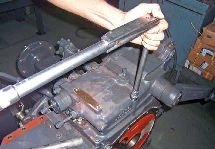
With the motor running at minimum RPM slowly raise the draft control lever (2). The adjustment of the draft lever (2) is correct when it is moved upward and this allows the arms to be completely raised.
NOTE: The position of the lever establishes only the position of the arms but does not influence the adjustment of the draft control lever (2).
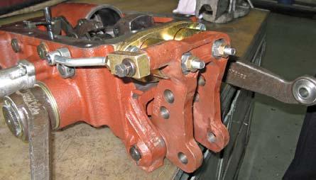
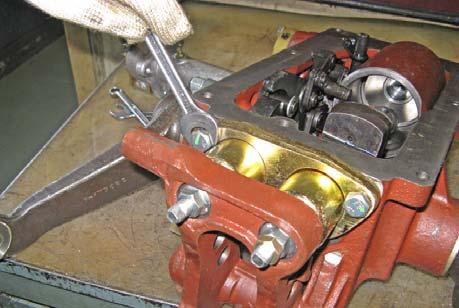
c)CONTROL OF ASSEMBLY OF REACTION SPRING
For a correct functioning of the rockshaft the top link bracket, when it is not working, must not have an axial play in the positive and negative. After having carried out a correct assembly, the spring holder (2) must rest against the rockshaft housing (1), while the spring holder cover (4) must rest against the flange (3).
In this condition the spring (M) is preloaded by about 1 mm. Before assembling the complete reaction assembly to the rockshaft housing a pre-assembly of the spring (M) is needed in order to obtain a measurement of about 11.7 mm.
After carrying out the reaction assembly a definitive adjustment is made. Keep the screw (V) fixed with an 8 mm wrench and adjust the self-locking nut (D) by tightening or loosening it gradually in order to eliminate the axial play completely.
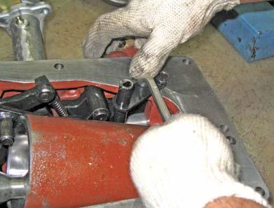
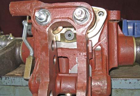
d)MEASUREMENT CONTROL OF INTERNAL PUSH ROD
If the rockshaft is disassembled and if the regulator (R) must be changed it is advisable to control the measurement (X) (15) in order to re-assemble the push rod in the same position. Ensure also that the measurement of the spring is 55 0/-0.2 mm.
The control of the measurement of the push rod with respect to the control valve face is carried out after making all the adjustments (sensitivity of control valve - position control lever - draft control lever).
With the rockshaft's arms completely lowered and without loads or implements on the three point linkage (neutral position), position the two control levers (1) and (2) at their lowest position against the backstop (F).
In this position push the push rod and verify with the appropriate gauge that the distance of 112 0/+0.5 mm is correct.
NOTE: If the measurement (X) is changed it is obligatory to carry out again the adjustment of the position and draft control levers.
Hydraulics
9.TORQUE DETAILS
Cap Screw Hydraulic Housing to Transmission Case
41-50 Nm (30-37 Lb-ft.)
Control Support Quadrant Linkage Screw
19-29 Nm (14-21 Lb-ft.)
Bracket Synchro Lubrication Mounting Bolt
8-10 Nm (6-7 Lb-ft.)
Compensator Linkages Cap Screw
88-98 Nm (65-72 Lb-ft.)

Hydraulics
9.TORQUE DETAILS (Contd.)
Control Support Assembly Mounting Screw
19-29 Nm (14-21 Lb-ft.)
Crank Locking Screw
19-29 Nm (14-21 Lb-ft.)
Cylinder Mounting Set Screw
98-127 Nm (72-94 Lb-ft.)
Cylinder Mounting Set Screw
68-88 Nm (50-65 Lb-ft.)
Hydraulics
9.TORQUE DETAILS (Contd.)
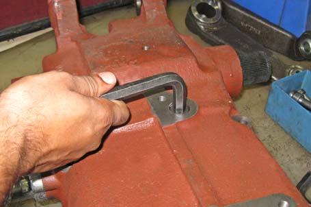
Tie Rod Mounting Screw
19-29 Nm (14-21 Lb-ft.)
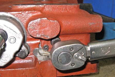
Top Link Bracket Mounting Screw
39-49 Nm (29-36 Lb-ft.)
Top Link Bracket Mounting Screw
39-49 Nm (29-36 Lb-ft.)
Control Valve Mounting Screw
19-29 Nm (14-21 Lb-ft.)
Drawbackscausesremedies
The Rockshaft lifts jerkilyInsufficient oil level in theTop up the level. tank.
Pump inlet filter clogged.Clean or replace the filter. Infiltration of air into theCheck the inlet pipe and pump inlet pipe.any coupling and gasket.
Rockshaft does not operateDifferential Valve blocked orRemove the control valve dirty.and unblock the regulator piston.
The rockshaft starts to lift,Tension rod measurementAdjust the draft control lever but it stops as soon as it“L” is not correct feels the load, without the functioning of the overpressure valve
The rockshaft does notFaulty adjustment of theAdjust position control descend over its entireposition control lever “1”lever travel.
Sensibility adjusted badlyAdjust sensitivity of Control Valve
The rockshaft does notDischarge Valve blockedRemove Control Valve and descend.unblock or clean discharge valve
Lifting capacity does notDeterioration of the ControlRemove control valve and match that prescribed.Valve seal rings.replace the external seal rings.
Relief and Safety valves outControl calibration of the of calibration.valves.
Poor pump efficiency.replace the pump Excessive loss of oil fromOverhaul the Control Valve Control Valve.
Drawbackscausesremedies
The Rockshaft supportsPiston gasket worn.Replace the gasket. loads with difficulty; there is a rhythmic oscillationDischarge Valve notAdjust the sensitivity of Control when the engine is on; theadjusted Valve or substitute the valve load descends when the engine is off. Oil leakage from SafetyRemove Control Valve and Valveadjust valve
Oil leakage from CheckRemove the Control Valve Valveand adjust valve
With the arms raised at backIncorrectly adjusted ofAdjust the position control stop and with the engine on,position control lever which,lever we have verified a rhythmicat maximum raised height, oscillation; with the enginecauses the internal off the load does not lowerautomatic back-stop to function
Working with the draftSensitivity of the ControlAdjust the sensitivity of the Control, the implement dropsValve is badly adjustedControl Valve too much or doesn’t stay in the groove
The draft control does notDraft control lever isAdjust the draft control lever function; the rockshaft raisesadjusted badly and lowers only with the position lever
The position control does notPosition control lever isAdjust the position control function; the rockshaft raisesadjusted badlylever and lowers only with the draft lever
Internal levers damagedOverhaul the rockshaft
Rockshaft does not liftPreselector is fully closedUnscrew fully the preselector and the relief valve acts“P” with the possibility to damage the pump
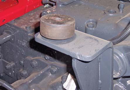
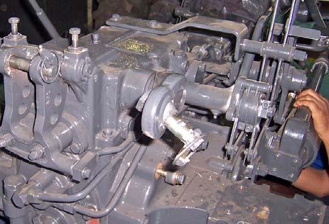
1.Remove rear isolator mounting bolt.
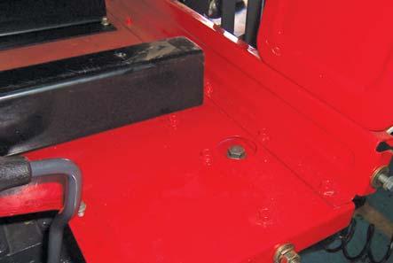
2.Then remove rear platform to front platform
11.REMOVAL AND REFITMENT OF HYDRAULIC LIFT UNIT bolts.
3.Remove the PC, DC, Range, Speed Lever Knobs and slow fast valve knob.
4.Remove diff. lock pedal.
5.Remove four wheel lever plate.
6.Remove fender to front platform bolts.
7.Remove ROPS connecting plate bolt.
8.Remove wiring connections and dismantle wiring from front platform.
9. Remove gear lever rubber boot and knob.
10.Lift the fender rear platform, sheet assembly. Removing of Control Levers
11.Disconnect necessary connections while lifting the assembly.
12.Then first dismantle all hydraulics pipes.
13.Remove hydraulic mounting bolts.
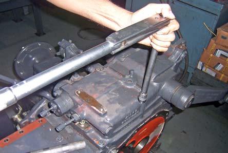
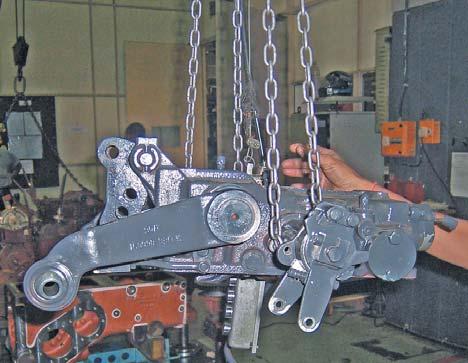
14.Lift the hydraulic unit assembly.
15.Make repairs as necessary.
16.Clean mating surfaces of housing assembly and differential housing using primer.
17.Install hydraulic lift unit using cap screws. Torque the bolt to 41-50 Nm (30-37 lbs.ft)
18.Connect lift unit supply line. Tighten to torque to 60 Nm (45 lbs.ft).
19.Install top link and connect lift links.
20.Follow the reverse sequence of dismantling for assembly.
Hydraulics
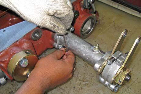
12.REMOVE, INSPECT AND INSTALL HYDRAULIC CONTROL LEVER SUPPORT ASSEMBLY


1.Remove Hydraulic Lift Unit as per the guided procedure.
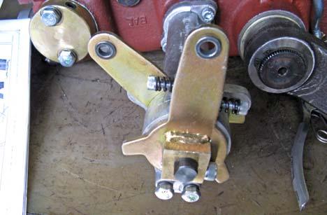
2.Remove position and draft control linkages levers by loosening lock clips and washers.
3.Remove socket head screw (A), two cap screw (B), lever position control (C) and hub (D).
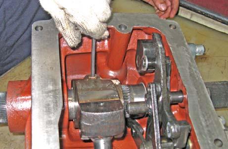
4.Loosen set screw (E) in link (F).


