
1 minute read
Lubrication Systems


c)Check the drive shaft to pump body clearance to specifications.
d)Check the drive pinion for wear or damage.
e)Check the gears for wear, damage or pitting. Burrs can be removed from the gears using a fine carborundum stone. The oil pump plate can if necessary be ground flat using surface and carborundum paste.
f)Check the backlash between the gears to specifications.
g)Check the clearance between the gears and end plate as follows : h)All sealing rings and gaskets must discarded. If the clearance is excessive check the end plate using a straight edge and feeler gauges. If necessary, the end plate can be ground flat using a sheet of crocus paper on a surface plate. Assemble the end plate and re-check the clearance. i)If no clearance exists, insert one additional gasket and re-check the clearance. j)Check the clearance between the oil pump drive pinion and the body after the pump is assembled (Fig. 4).
1.Install the gear case on the pump body using a new gasket.
2.Install the gears, then place a length of plastigauge across the top of each gear.
3.Install the end cover using a new gasket and tighten the bolts to the specified torque.
4.Remove the cover and measure the thickness of the plastigauge. This must not exceed the dimension given in specifications.
6.ASSEMBLY : LOBE TYPE PUMP
Install the rotor shaft assembly in the oil pump body. Fit the key in to the shaft and press in the drive gear with that in the shaft. Drive in a new roll pin. Install the outer rotor. Install the pump end over and tighten the bolts to the correct torque. Assemble the screen to the pump and tighten the bolts to the correct torque. Assemble the relief valve inside the pump body and install the spring. Tighten the retaining bolt using a new washer.
Lubrication Systems
7.INSTALLATION a)Install the oil pump in the crankcase then tighten the bolt to the correct torque. b)Use liquid gasket (loctite 584) and Adapter plate. Install the crankcase oil pan, tightening the bolts to the correct torque. c)Fill the crankcase with the correct grade of lubricating oil to the oil level mark on the dipstick.
8.LUBRICATING OIL FILTERS
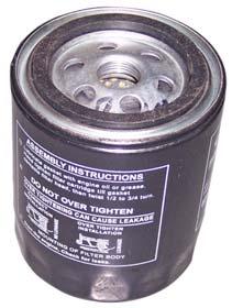
1.REMOVAL a)Unscrew the spin-on oil filter from filter head and install new filter. b) Service Schedule :
NOTE: Engine Oil and filter element must be changed after every 200 hours of engine operation.
For new tractor and overhauled engine first service - Oil filter replacement after 200 hrs. It is highly detrimental to engine reliability, if cartridge is reused by reflushing with cleaning solvent. Dispose off immediately.


