
1 minute read
Electrical System


B.STARTER MOTOR
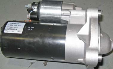
1. Introduction
Self Starter is used for cranking the engine. The starter described here is pre-engaged type. This starter is designated as ‘Pre-engaged’ since the drive goes into complete mesh with the Ring gear before the full power torque of the starter motor is developed. The main feature being prevention of premature ejection of the pinion by the flywheel during intermittent firing pulses of the engine.
2. Description and Principle of Operation
The starter is 4-pole, 4 brush, earth return machine with parallel connected field. Main parts are i) DE bracket assy, ii) Drive assy, iii) Intermediate bracket assy, iv) Armature assy, v) Solenoid switch assy, vi) yoke & field coil assy, vii) commutator end bracket assy, viii) brush gear assy. When the ignition switch is operated (refer Fig. 2). The solenoid switch mounted on starter motor gets energised and the plunger gets pulled. An actuating lever whose top end is linked with the plunger, bottom end is linked with the drive and centre is supported on the eccentric pin, pushes the drive into mesh with the flywheel ring gear when the solenoid is energised. At the end of the travel of the plunger a pair of contacts close connecting the starter to the battery directly, this bye-passes the series winding (also called as operating winding) of the solenoid Shunt winding (also called hold-on winding) which is energised as long as ignition switch is on holds the plunger in position. As soon as the engine fires and the ignition switch is released, the solenoid is released and supply to starter is cut off. This also disengages the drive from the ring gear.
a. Drive Assembly
The drive assembly transmits the torque developed by the armature to ring gear. The roller clutch arrangement of the drive prevents armature from being rotated at an excessively high speed in the event of pinion remaining in mesh with the ring gear when the starter is on. The clutch operates on the principle of wedging of cylindrical rollers between two converging surfaces. The convergent form is obtained by matching cam tracks on a cylindrical surface. The clutch consists of 5 rollers which run on cam track cut in inner member which is driven by the armature. The pinion is an integral part of the outer member.
1Main Terminal (Sol.)
2Terminal Base Assy.
3Spindle Assembly
4Plunger Return Spring
5Sealing Ring (Sol.)
6Solenoid Switch
7Plunger Assembly
7AShroud
8Screw (Sol. Fixing)
9Connector
10Seal
11Sealing Ring (C.E. & D.E.)
12Intermediate Brkt. Assy.
13Oil Seal
14Engaging Lever Assembly
15Jump Ring (Pinion)


