14 minute read
Single Parts Repair, Off-Season Inspection or General Overhaul


Overhauling a tractor could be essentially different in the following respects :
1)The repair of individual parts that has failed during operation. This kind of repair is by no means as easy as it may seem at first sight, for replacing the defective part may call for elaborate and extensive dismantling and reassembly procedures. Another disadvantage of a “single parts repair” is that it may have to be carried out during the working season when the tractor is most urgently needed. When taking the preventive maintenance measures as outlined below these “single parts repairs” should, to a great extent, be eliminated.
2)A fundamentally different procedure is the “off-season inspection” when all parts of the machine are checked over. This procedure covers mainly the following : Thorough cleaning of the machine, re-setting and adjusting of all units subject to a certain amount of wear, replacing those parts which still function but show such a degree of wear that they are not likely to survive the ensuing working season. Off-season inspection is a thorough preventive maintenance measure. It calls for a well trained serviceman with a detailed knowledge of the tractor and the functioning of the various units.
Off-season inspection is the best guarantee for trouble free and efficient performance. Repairs as described in foregoing and following chapters can be prevented. The term “off-season” applies generally to the winter months when the tractor is seldom required to do any work. During this period service stations do not have much to do as a rule and can give better service than during the peak periods.
3)A rather expensive reconditioning job is the “general overhaul”. It becomes necessary when the tractor has been kept on the job by “make-shift” repairs without observing fundamental maintenance rules. Worn parts fail and other, potentially good parts are often broken as a result of these failures.
Apart from being a costly affair it very often happens that this sort of repair has to be made during the operating season when work is pressing. A general run down condition, moreover, often causes small fissures and cracks which can be overlooked and are then the source of fresh trouble.
Off-season inspection is the most important measure of preventive maintenance. The frequency of this inspection should be determined by the number of operating hours and by operating conditions.
General Recommendation for disassembly and assembly operations
Before the tractor is accepted in the workshop, all external surfaces must be thoroughly cleaned. The service station must be clean and well lit. Strict cleanliness must be observed when engine, transmission and hydraulic systems are repaired.
A tractor repair shop should not be without at least one good lifting crane so that engines and transmissions can be removed and installed without hazard. Suitable wooden mounting blocks, easily accessible from all sides, on which engines and transmissions can be placed, should be available. They can easily be made locally.
Before dismantling, drain all water, fuel and oil from the tractor.
It is good practice to check compression of each cylinder before dismantling the engine to get general ideal on the condition of the compression building elements, such as pistons, sleeves, gaskets, etc.
A comparison of compression readings of these figures will disclose errors or show improvements.
Whenever reference is made to “Cleaning” in the various sections of this book it should be taken mean thorough cleaning i.e. complete removal oil, grease, impurities, foreign matter and burr etc. Even the smallest contaminants may cause serious trouble!
Follow the disassembly and assembly procedures in this book. They are based on years of practical experience and provide the quickest reliable repair procedure.
After removing oil, grease, etc., arrange parts on a clean table in the order in which they belong to prevent confusion later. A suitable installation to remove oil, grease, dirt etc. from parts should be available in every tractor repair shop.
A small boiler and a good solvent are ideal for this purpose.
Before reassembly, carefully inspect all parts whether they can be re-used. Ball and roller bearings must be washed in kerosene. Before reassembly, carefully inspect all parts to see whether they can be re-used. Replace if necessary.
Ball bearings must be thoroughly cleaned and well dried before inspection. To determine the degree of wear on a ball bearing, hold the inner race with your hand and spin the outer race. The sound emitted by a good ball bearing is very weak and similar to that of finger tips gliding over glossy paper. A badly worn bearing makes a rattling, chain-like noise.
Do not remove the original oil paper wrapping from new ball bearings until just before sliding them on shafts. The grease coating applied by the bearing factory must not be removed unless this is necessary for cleanliness reasons.
Warm press-fit ball bearings in clean 80 0 C (175 0 F) oil and slide them on shafts as quickly as possible.
When assembling, apply some transmission oil to all moving parts, especially to bearings, to provide an oil film until the regular pressure feed lubrication takes over.
In order to eliminate errors all steps, such as adjustments, settings, and the various phases of assembly and disassembly procedures, must be considered without haste and with common sense. It is better to check three times than commit one error.
Put all new felt seals and gaskets in 50 0 C. (122 0 F) warm oil and allow to soak before installing them. Apply some soft soap or soap solution to all rubber hose connections before installation.
Always install oil seal with the sealing lip towards the oil side. Prior to assembly apply some engine oil to the sealing lip. Generally oil seals are a press fit in their bores and the steel casing is slightly compressed in assembly. Used oil seals have lost tension and the required pressfit can no longer be obtained. For this reason, never reuse oil seals even though the sealing lip may still be in good condition. Should an emergency arise, install the reused oil seal with some liquid sealer.
Expansion plugs should be oil tight. Use some sealing compound and fit the plug with its concave side out. Spread the plug by driving carefully on its center with suitable installing tool.
Secure all nuts by using good spring lock washers or external tooth lock washers except for cylinder head, brass and castellated nuts, which are secured by special methods.
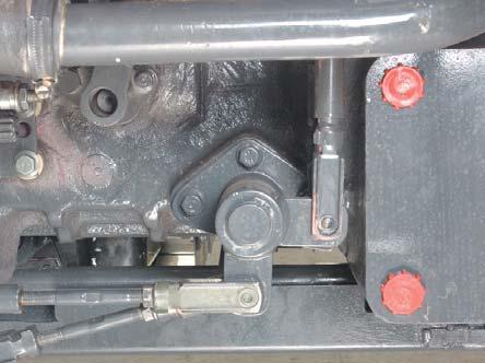
Gaskets and O-rings must be replaced during reassembly. Apply grease to new O-rings or oil seals before assembling. See the figure left side.
When reassembling external snap rings or internal snap rings, they must be positioned so that sharp edge faces against the direction from which a force is applied. See the figure left side.
To prevent damage to the hydraulic system, use only specified fluid or equivalent.
Castellated nuts must be carefully secured with cotter pins. Spread cotter pins as shown on the right nut below. Be sure that pins seat tightly so that they will not work loose.
When reassembling external snaprings or internal snaprings, they must be positioned so that sharp edge faces against the direction from which force is applied. (See fig.) When inserting spring pins, their splits must face the direction from which a force is applied. (See fig.)
After every overhaul or major repair the tractor should be given new coat of paint. The importance of this should not be underrated, as moisture, rust and corrosion have access where bolts and nuts were loosened and the original paint coat has been broken. The original paint (Tractor Red) is available at all Establishments.
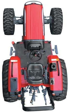
For all procedures described in this manual a certain amount of skill and craftsmanship is required. Wherever the terms RIGHT and LEFT are used they are understood to mean the right and left sides when facing forward in the tractor seat. Reference to FRONT indicates the radiator end of the tractor and REAR the drawbar end.
Priming the Lubrication System
NOTE : Diesel engines must not be rotated when priming with oil; otherwise, they are likely to start running.
When assembling the overhauled engine, it is necessary to thoroughly lubricate the various running parts with clean engine oil to assure initial lubrication when engine is first started. However, to further make certain that complete initial lubrication is available, the engine lubricating system should be pressure primed or charged with oil. Attach the line from a priming device to a suitable fitting located in the main oil gallery, filter header or oil cooler of the engine and inject sufficient oil into the engine to fill the oil filters and charge the entire system. Use only clean engine oil in accordance with Operator’s Manual. New or overhauled engines that have been in storage over an extended period should also be primed in a similar manner.
After the priming procedure is completed, make certain that the oil level is checked before the engine is put into service. Do not overfill the engine; neither should engine be short of oil as a result of using the pressure priming procedure.
Priming the engine will minimize the possibility of scuffing or heat build-up in the running components which could lead to immediate or low hours of use failures.
Engine Run-in Schedule
NOTE : Do not run the engine at low or high idle speeds for long period after installing new rings or sleeves, as rings will not seat during idle operation.
Start
Prior to starting make sure, that a)all bearings are pre-lubricated b)the crankcase is filled with specified engine oil c)the cooling system is filled correct level d)Precautions for alternator operation are observed.
Run-in
1.Start and run engine at 3/4 rated engine speed with no load, until operating temperature (80-850C) (164-1720F) is reached, cover the radiator if necessary, DO NOT run for over 10 Minutes.
2.Retorque cylinder head bolts.
DO NOT run the engine longer than 15 Minutes, before retorquing cylinder head bolts.
3.Continue according to the following chart. with Dynamometer rated speed8010
100 below rated speed5010 without Dynamometer
(In-Vehicle Run-in Procedure)
3/4 of ratedlight5
3/4 of ratedmedium15 rated speedfull20
After Running-in
Retighten manifold bolts and/or stud nuts.
Re Torque the cylinder bolts and check valve clearance and readjust as necessary.
Handing over the Engine
In the presence of the operator check engine oil level and coolant level. Test run the engine. Point out to the operator that the overhauled engine is to be treated in the same way as a new one.
Check And Maintenance
Be sure to check and service the tractor on a flat and clean place with engine shut off, parking brake on and blocked wheels.
(1)Daily check
To prevent trouble from occurring, it is important to know the condition of the tractor, check the following items.
Checking
•Checking areas where previous trouble was experienced.
•Walk around the tractor.
1.Check the tire pressure and check for wear and damage.
2.Check for oil and water leakage.
3.Check the engine oil level.
4.Check Transmission fluid level.
5.Check coolant level.
6.Check and clean the radiator screen and grill.
7.Check the condition of ROPS attaching hardware.
8.Check the bolts & Nuts of the wheels.
9.Condition of danger, warning and caution labels.
10.Clean around the exhaust manifold and the muffler of the engine.
11.Check fan belt tension.
•While sitting in the operator’s seat
1.Check the working condition of the throttle pedal, brake pedals and clutch pedal.
2.Check the parking brake.
3.Check the steering wheel play.
•After Turning the switch Key
1.Check the Headlights, taillights and hazard lights clean it necessary.
2.Check the performance the meters and gauges.
•After Starting the engine
1.Check the colour of the Smoke.
2.Check the brakes for proper operation.
Check Points
Wheel Mounting nuts checking
•Never operate tractor with untightened rim wheel.
•Check all bolts and nuts frequently and keep them tight.
Checking Radiator hoses and clamps .
-If hose clamps are loosen or water leaks, tighten clamps securely.
-If radiator hoses are swollen, hardened or cracked replace hoses and clamps.
-Check all power steering line, fuel line, clamps and hoses.
-If these found damage, replace them.
2.Transmission &9.2 / 36.8SAE 75W UTTOSAE 80W UTTO listed above.
3.Lubrication FittingsC. L.NLGI No. as recommended
Front Axle - Front Wheel “Toe-in” Check
In the event of the tie rod setting, then it is necessary to adjust the TOE-IN. Before measuring and adjusting the TOE-IN, ensure the front wheels are in the straight ahead position and the front axle is not tilted.
After adjusting the front wheel tread and with all connections secured, the front wheel Toe-in shall be as follows,
Toe-in Value
35 SeriesInchmm
4WD0 – 0.230 – 6
Measure the distance between the outer edges of the wheel rims at the same height as the hub caps. Mark the point measured and turn the wheels half revolution so that the marked points are at the rear. Measure again the distance between these two points and this distance must be the same as measured before without variance. To adjust the TOE-IN shorten or extend the tie rod clockwise or anti-clockwise.
When the TOE-IN adjustments have been made the tractor should be jacked-up and the axle tilted to its maximum tilt position. In this position the wheels should be turned to the full left-hand lock and at this angle the welded stop on the steering knuckle pivot pin sleeve should be hard against the stop on the steering knuckle.
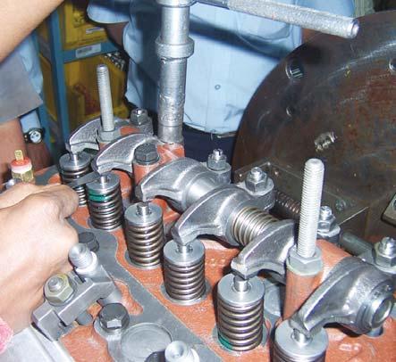
Adjusting Valve Clearance
Adjusting Engine valve clearance at every 800 hours. To check valve clearance use the simplified procedure as out lined in the following.
All Values can be adjusted by cranking the engine only twice.
No 1 Piston at T.D.C. (Compression)
Adjust Valves (Engine Warm)
1245
No 4 Piston at T.D.C Compression
Adjust Valves (Engine warm)
3678
Inlet0.010 inch (0.25mm)
Exhaust0.012 inch (0.3mm)
SOP for Rotary FIP timing checking on tractor
1.Remove engine starter.
2.Ensure that the position of timing pointer on front cover which mets with crank pulley punched line.
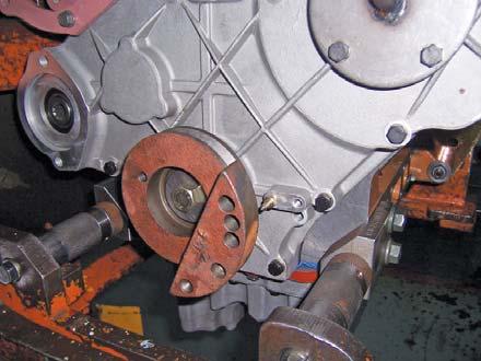
3.Remove high pressure pipe at Fuel injection pump end.
4.Remove special plug provided at backside of FIP & insert dial (ASN0600G013) with adapter as shown in Fig.1.
5.Rotate crankshaft pulley in clockwise direction (as seen from flywheel side) till the pointer matches with crankshaft pulley groove. Ensure first cylinder piston at compression TDC.
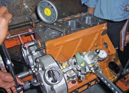
6.Set dial gauge to read zero at above match position.
7.Rotate pump gradually to upward / downward direction till dial gauge showing specified reading.
Injection Timing (mm@tdc)
For 4035 / 3535—0.95 ± 0.02 mm
For 4535 / 5035—1.00 ± 0.02 mm
SOP for adjusting Clutch Pedal Free Play

Measure free play of pedal stroke (A). Ensure free play is within specified limits. If free play is not within specified limits, adjust clutch linkage as shown below.
Free Play - Distance 0.78 to 0.98 inch (20 to 25 mm)
1.Loosen jam nut (B).
2.Turn the turn buckle (C) anticlockwise (from eyesight view) to decrease play and clockwise to increase play.
SOP for adjusting Brake Pedal Free Play
Measure free play of pedal stroke (A). Ensure free play is within specified limits. If free play is not within specified limits, adjust brake linkage as shown below.
Free Play - Distance 1.57 to 1.77 inch (40 to 45 mm)
1.Loosen jam nut (B).
2.Turn the Turn Buckle (C) anticlockwise to increase play and clockwise to decrease play.
Flushing cooling system and changing coolant
Do not remove the radiator cap when the engine is hot. After cooling the engine, loosen the cap slightly (one step) to relieve excess pressure before removing cap completely.
1.Stop the engine and let it cool down.
2.To drain the coolant, loosen the radiator cap slightly first to allow pressure to reduce. Then remove radiator cap completely. Open the drain plug at bottom RH side of radiator to drain the coolant. Place a tray to collect the coolant.
3.After all coolant is drained, install the hose securely.
4.Fill with clean water and cooling system cleaner solution.
5.Follow direction of the cleaner instruction.
6.After flushing, fill with clean water and anti freeze until the coolant level is just below the port.
7.Fill with clean water and anti freeze up the upper line of surge tank.
8.Install the radiator cap (1) securely.
9.Start and operate the engine for few minutes.
10.Stop the engine check coolant level and add coolant if necessary.

NOTE :
•Do not start engine without coolant
•Use clean water and anti freeze to fill the radiator as per abient temperature mixing ratio.
•Securely tighten the cap. If the cap is loose or Improperly fitted, water may lead out and cause the engine overheating.
Anti Freeze
Frozen water can damage the cylinders and radiator. It is necessary, if ambient temperature falls below 0 0 C (32 0 F) to remove cooling water after operating or to add anti freeze to it.
Refer to SAE J1034 and SAE J814C for the procedure of mixing water and antifreeze.
NOTE :
•When the cooling water level drops add only clear water. In case of leakage, add anti freeze and water is the specified mixing ratio.
•Anti freeze absorbs moisture keep unsealed anti freeze in the lightly sealed container.
•Do not use radiator clearing solution when anti freeze has been added to the cooling water. (Anti freeze contains an anti corrosive agent, which will react with radiator cleaning agent forming sludge which will affect the engine parts)
Note : Drain water once in a week or earlier if water contamination is excessive. Continued driving with water accumulation in fuel filter will cause damage to fuel pump / other fuel system components.
Note : Replace fuel filter at the recommended period or whenever it gets clogged. Discard the old filter and do not repair or clean the filter.
Always fit the spin-on filter dry.
Do not hold key at engine start position for more than 10 seconds continuously. If more engine cranking is needed try again after 30 seconds.
Always close the air vent screw except for bleeding fuel lines other wise, engine will run irregularly or stall frequently.
Bleeding Fuel System
Air must be removed
1)When the fuel filter or lines are removed.
2)When water is drained from fuel filter.
3)When tank is completely empty.
4)When tractor is not used for a long period of time.
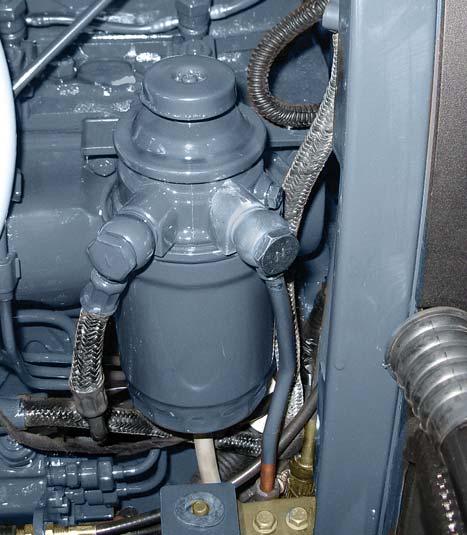
Fuel filter provides clean, moisture free fuel for the injection process. A hand primer is provided to manually remove excess air from the fuel filter and fuel lines.
Major Components:
•Hand Primer (F)
•Air Bleeding Screw (G)
•Fuel Filter (D)
Fuel enters the filter at inlet (A) and flows through the filter element separating water if contents before flowing through outlets (B) to the fuel injection pump. Since water and contaminants settle at the bottom of the sediment bowl, a drain plug is provided at the bottom of the filter. Drain water in fuel, by loosening drain plug once every 50 hrs. of operation.
To drain water in fuel, loosen the drain plug upto 1 or 2 turns. During loosening drain plug, place a small tray to collect the water coming from pipe (C). Retighten the drain plug by hand.
Servicing the fuel filter
1.It is recommended to replace the fuel filter every 500 hrs.
2.To remove Filter, unscrew the filter (D) from adaptor (E).
3.Check O'rings of fuel filter for any crack / damage. Smear oil on the new O'ring before installation.
4.Clean the adaptor with clean diesel from inlet and outlet. Ensure no dirt, foreign particles entangled in flap valves or filter head.
5.Assemble the new filter. Do not over tighten.
6.Prime the system and bleed the filter. Tighten the bleeding screw.
Check Radiator Hose Connections & tighten if required
Check Fan Belt Tension and adjust if necessary
Flush Cooling System
ELECTRICAL SYSTEM
Clean Battery Terminals
Check Starter Motor and Alternator Carbon
Brushes and replace if necessary
TRANSMISSION / HYDRAULIC SYSTEM
Check Oil Level and top-up if necessary
Change Transmission Oil
Change Suction Filter Element
Clean Strainer (During every oil change) #
Change Strainer Every 2000 Hrs.
AXLES, WHEELS AND TIRES
Check Tire Pressure and inflate if necessary *
Torque Wheel Nuts #
Check Front Axle Oil Level
Change Front Axle Oil Every 1000 Hrs.
STEERING
Check Steering Wheel Play Every 500 Hrs.
Set Toe-in
CLUTCH AND BRAKES
Check and adjust Brake Pedal Free Play * Periodically
Check and adjust Clutch Pedal Free Play *
GREASE ALL NIPPLES *
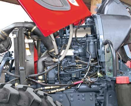
Splitting Between Front Axle & Engine
SPLITTING BETWEEN THE FRONT AXLE AND ENGINE
1.Using the special tool - Rail & Trolley Jack - support the Engine assembly. Apply Tractor parking brakes and place wedges to hold the rear wheels. Drain the water from the Radiator, from two places: a.Engine Block side drain plug. b.Radiator bottom tank drain plug.
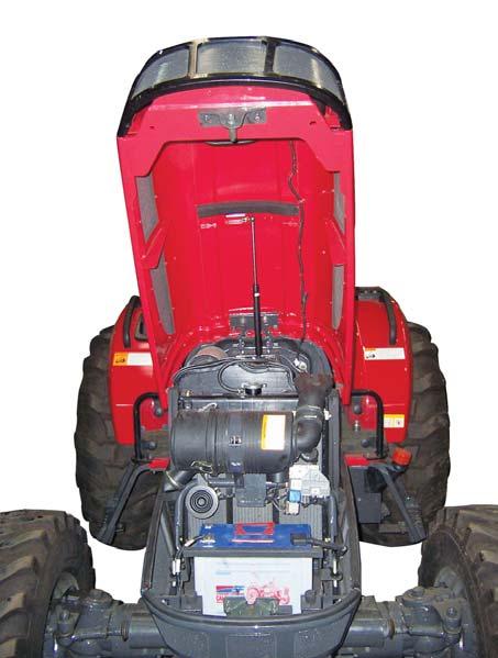

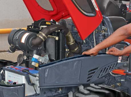
2.Open the hood. Negative (–) Positive (+)
3.First remove the battery cable from its negative terminal & then remove battery cable from positive terminal. Remove the battery.
NOTE : Always disconnect the negative terminal first.
Splitting Between Front Axle & Engine
4.Disconnect the gas spring from hood and then remove hood from hinge assembly.
5.Remove side panels from locating points.
6.Disconnect horn.
7.Loosen the Air cleaner inlet hose, connections from the intake manifold and air cleaner.
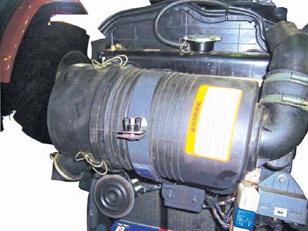
8.Remove air cleaner by removing it from bracketaries.
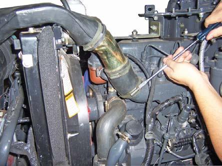
9.Remove the radiator inlet and outlet hoses.
Splitting Between Front Axle & Engine
10.Remove the radiator mounting bolts and remove the radiator.
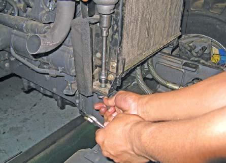
11.Remove the front bottom grill and bonnet locking bracket.
12.Disconnect the LH / RH hoses to the power steering cylinder and plug the hoses to prevent oil spillage.
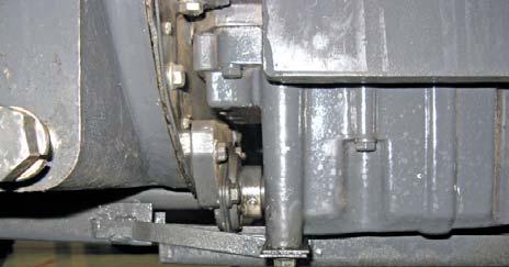
13.Remove the propeller shaft guards.
14.Remove the propeller shaft bearing from support bracket.


