2 minute read
Timing Gear Train, Front Cover & Camshaft


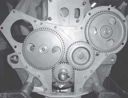
C.TIMING GEARS
1.REMOVAL a)Timing Gear Cover b)Remove the front cover. c)Remove the nut (1-2) then remove the injection pump gear (2-2). d)Remove the idler gear shaft bolt (3-2) then remove the idler gear (4-2) and shaft. e)Using a suitable puller remove the crankshaft pinion and key. f)Remove the camshaft gear (6-2).
To remove the timing gear cover, first remove the front support, axle and radiator assembly as follows : Drain cooling system, raise hood and disconnect headlight and horn wires at junction on front support, then unclip loom from radiator. Remove hood pivot bolts and remove hood. Do not lose the pivot bolt spacers. Disconnect radiator brace. Disconnect upper and lower hoses from radiator. Disconnect the drag link. If tractor is equipped with hydrostatic steering, disconnect the steering cylinder hoses, then cap and plug all openings to prevent dirt from entering system.
Then, on all tractors, place wood blocks between steering gear housing and axle to prevent tipping. Using a suitable jack, support tractor under clutch housing. Unbolt stay rod bracket from clutch housing and steering gear housing from front of engine. Raise engine until crankshaft pulley will clear front axle support. Then roll out from axle support with front axle and tires.
2.INSPECTION AND REPAIR
a)Inspect the gears for wear and cracked or chipped teeth. Remove any burrs on the gears with a fine carborundum stone.
b)Inspect the fan drive pulley for wear or cracking.
c)Check the fit of the idler gear and shaft to specifications.
d)Check the condition of the idler gear shaft bolt thread insert in the front of the crankcase. If inspection proves if necessary remove the thread insert and fit a new one.
Timing Gear Train, Front Cover & Camshaft
3.INSTALLATION
a)Fit a new key to the crankshaft then press the crankshaft pinion on to the crankshaft.
b)Assembly the idler gear and shaft, install it on the crankcase ensuring that the double marks on the idler gear line up with the double marks on the crankshaft pinion. Tighten the bolt to the specified torque.
c)Install the camshaft and camshaft gear.
d)Install the injection pump gear ensuring that the double marking on the injection pump gear is in register with the single marking on the idler gear, install the three bolts and tighten to the correct torque.
D.CAMSHAFT
1.REMOVAL
NOTE 1:Before camshaft removal check a.Backlash of camshaft drive gear b.Camshaft end float c.Cam lobe lift a)Remove the valve rocker arm shaft assembly. b)Lift out the valve push rods and identify them so they can be installed in their original positions. c)Remove the crankcase front cover. d)Remove the oil pump. e)Invert the engine then turn the camshaft until the cored holes in the gear line up with the bolts (7-2) securing the camshaft thrust plate then remove the bolts and lockwashers. f)Withdraw the camshaft with gear from the crankcase. g)Remove the valve tappets (1-4) and identify them so they can be installed in their original positions.
NOTE 2:Cam lobe lift may be checked by means of a dial indicator gauge.
Rest the stylus of the dial indicator on one of the push rods.
Rotate the engine one revolution and note dial indicator reading. Compare reading with “specifications”.


