5 minute read
Steering


6.Further tap the rod till the piston comes out.
7.Inspect the piston seal and bearing ring for wear or cracks.
8.Remove wear or damaged seal or ring and install with new one. If these seals or O'Rings damaged, this will result into external leakages/free wheeling problem.
Steering Cylinder Refitment
1.After installing new seals and o’ring on piston and cylinder head, tap gently by plastic hammer the rod to align it to cylinder housing face mounting bolt.
2.Tighten the allen screw of cylinder head to cylinder housing as per the specified torque. (i.e.25Nm / 18 lb.ft.)
NOTE:Whenever dismantling of steering cylinder for inspection/checking always replace piston seal, head cover seals, rod seals, wiper ring and O’Ring (Seal Kit).
9.TROUBLE SHOOTING
Most steering problems can be corrected if the problem is properly defined. The entire steering system should be evaluated before removing any components. The steering control unit is generally not the cause of most steering problems. The following is a list of steering problems along with possible causes and suggested corrections.
TROUBLEPROBABLE CAUSEREMEDYREF.
A.Slow steering, hard steering, or loss of power assist.
Worn or malfunctioning pump.Replace pump.
Malfunctioning relief valveReplace the relief valve. allowing the system pressure to be less than specified.
Overloaded steer axle.Reduce load.
B.WanderVehicle will not stay in a straight line.
Air in the system due to lowCorrect. level of oil, cavitating pump, leaky fitting, pinched hose, etc.
Worn mechanical linkage.Repair or replace.
Bending of linkage or cylinder rod. Repair or replace.
Wear in steering control unit. Replace the steering control unit.
C.Drift - Vehicle veers slowly in one direction.
D.Slip - A slow movement of steering wheel fails to cause any movement of steered wheels.
E.Temporary hard steering or hang-up
Worn or damaged steering linkage.Replace linkage and align front end.
Leakage of cylinder piston sealsReplace seals or accessory valve. or accessory valve between cylinder lines or ports.
Worn steering control unit meter.Replace steering control unit.
Thermal Shock *Check unit for proper operation and cause of thermal shock.
9.TROUBLE SHOOTING (Contd.)
TROUBLEPROBABLE CAUSEREMEDYREF.
F.Erratic steering
Air in system due to low levelCorrect condition and add fluid. of oil, cavitating pump, leaky fitting, pinched hose, etc.
Loose cylinder piston.Replace cylinder.
Thermal shock damage. *Replace steering control unit.
Sticking flow control spool.Replace flow control valve.
G.“Spongy” or soft steering
Air in hydraulic system. MostBleed air out of system. Placing likely air trapped in cylindersports on top of the cylinder will or lines.help prevent air trapping.
Low fluid level.Add fluid and check for leaks.
H.Free Wheeling - Steering wheel turns freely with no feeling of pressure and no action on steered wheels.
Steering control unit meter hasUsually starting engine will cure a lack of oil. This can happenproblem. on start-up, after repair, or long periods of non use.
No flow to steering unit can be caused by:
1.Low fluid level.Add fluid and check for leaks.
2.Ruptured hose.Replace hose.
3.Internal steering control unitReplace the unit. damage due to thermal shock*.
I.Free Wheeling - Steering wheel turns with slight resistance but results in little or no steered wheel action.
J.Excessive free play at steering wheel.
Leaking relief valveRepair or replace the accessory in cylinder lines.valve.
Piston seal blown out.Determine cause. Correct and replace seal.
Loose steering wheel nut.Tighten the nut.
Steering column shaft worn orRepair or replace steering wheel damaged. There should be veryconnection or column. little free play in the unit itself.
9.TROUBLE SHOOTING (Contd.) TROUBLEPROBABLE
K.Excessive free play at steered wheels.
Broken or worn linkageCheck for loose fitting bearings between cylinder and steeredand anchor points in steering wheels.linkage between cylinder and steered wheels.
Leaky cylinder seals.Replace cylinder seals.
L.Binding or poor centering of steering wheel.
High back pressure in tank lineRevise circuit return line. can cause slow return to center. Should not exceed 300 psi.
Large particles can causeClean the unit and filter the oil. binding between the spoolIf another component has failed and sleeve.generating contaminants, flush the system while bypassing the steering control unit.
M.Steering unit locks up.
Large particles in meter section.Clean the unit.
Insufficient hydraulic powerCheck hydraulic power supply. (units over 15 in 3 ).
Severe wear and/or broken pin.Replace the unit.
*Thermal shock.Replace the unit.
N.Steering wheel oscillates or turns by itself.
O. Steered wheels turn in wrong direction when operator activates steering wheel.
P.Steering wheel kicks at start of steering.
Parts assembled wrong.Correct it. Steering unit improperly timed.Correct timing. Lines connected to wrong ports.Reconnect lines correctly.
Lines connected to wrongReconnect lines correctly. cylinder ports.
No inlet check valve onInstall a check valve. steering control unit.
*Thermal shock - A condition caused when the hydraulic system is operated for some time without turning the steering wheel so that fluid in the reservoir and system is hot and the steering control unit is relatively cool (more than 50 0 C temperature differential). When the steering wheel is turned quickly the result is temporary seizure and possible damage to internal parts of the steering control unit. The temporary seizure may be followed by total free wheeling.
1.SPECIFICATION a)Pump
1.Make---------------------------------------------------------- EATON
2.Type----------------------------------------------------------- Gear
3.Output @ 2800 RPM ------------------------------------ 41 lpm (11 gpm) b)Hydraulic Lift Unit
1.Make---------------------------------------------------------- MITA
2.Lift Cylinder ID --------------------------------------------- 85 mm
3.System Relief Valve Pressure @ 40 lpm ----------- 200 (+5/-0) bar
4.Shock Load Relief Valve Setting ---------------------- 225 - 230 bar
5.Bell Crank Pin Hole --------------------------------------- 19.5 mm
6.Suction Strainer Size ------------------------------------- 100 mesh
7.Suction Filter Size ----------------------------------------- 10 micron
Features i)Position and Draft Control ii)Lowering speed adjustment of Lifting Arm iii)Common oil for Transmission, Hydraulic and Power Steering iv)Common Relief Valve for Hitch Valve, Auxiliary Valve and Loader Valve
TECHNICAL FEATURES
•Operation with draft and position control.
•Reading of traction force on top link.
•Adjustment of operating sensibility during draft control work.
•Lowering speed adjustment of lifting arms.
•Safety transport lock on control valve.
•Automatic hydraulic limit stop of angular excursion of lifting arms.
•Sector control with two levers: One lever for the position and one for the draft control.
3. HYDRAULIC OPERATION
1. GENERAL DESCRIPTION
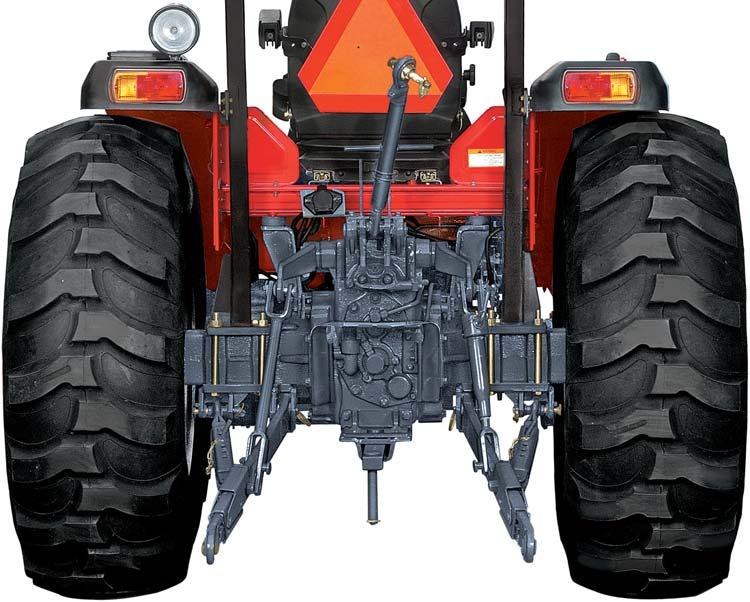
These tractors are equipped with hydraulic system consist of an engine driven gear pump, lift housing, connecting pipes and the filter. The reservoir is transmission housing. The oil used is common for transmission, hydraulics and Brakes. A strainer is fitted on transmission. Addition paper filter is incorporated on suction line which ensure 100% filteration. Lift housing houses lift cylinder, control valve, shockload relief valve, control valve linkages, and Rock shaft. A pivot bracket in the rear has two holes for different draft sensitivity, carries a toplink. Heavy duty top link, collapsible type lower links, telescopic stabilizer jug & collar lift rods are provided as part of 3 point linkage.
2.PRINCIPLE OF OPERATION
The direction of oil flow is from strainer, filter, pump, Auxiliary valves, control valve to lift cylinder. The lifting of the system is protected by a relief valve between the pump & control valve. The cylinder of the system is protected by shock load relief valve. The control valve is operated by two levers.
Thus the only flow delivered to the cylinder is that controlled by the lever in use. The inner lever controls the implement draft and outer lever controls the implement position. When the spool is in neutral or hold position the fluid passes through unloading valve to go to tank. Unloading
When spool is in lift position the part of fluid passes to the opposite side of unloading valve. Making unloading valve pressure more than working pressure. Then the fluid passes through non return valve to the lift cylinder and rest of fluid passes through flow control valve to tank.
When spool is in lower position the fluid passes through unloading valve to tank. The oil trapped in the cylinder passes through lowering valve to tank.


