1 minute read
Differential Lock System


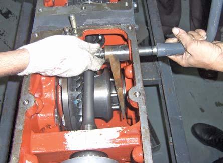
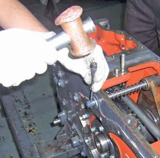
2.Removal a.Remove Differential lock arrangement as per the procedure given in differential section. b.Remove differential lock pedal shaft (A) by removing spring pin (B). c.Use Special Tool (C) to remove spring pin. d.Remove fork spring lock pin (D). e.Hold spring and differential lock fork and pull differential cross shaft from RH side.
Differential Lock System

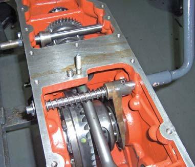
3.Assembly a.Fit oil seal at LH side. b.Insert differential lock shaft, assemble spring. c.Assemble fork, locating in differential lock coupling. d.Insert spring dowel near fork. e.Insert washer and spring dowel at LH side.
NOTE: Clean all parts and check the spring tension orcracks. If necessary replace it. Replace O’ rings and oil seals.
4.Installation a.Installation is reverse procedure of Removal.
- 5
A.REAR PTO COVER 1.DISMANTLING
a.Loosen bolt (A) of rear PTO cover (B).
b.Loosen bolt (C) of plate retainer (D).
NOTE: Hydraulic Housing on top of transmission case to be removed for dismantling of Rear PTO Cover.
c.Now take out rear PTO cover from locating pins by slight tapping.
2.ASSEMBLY
a.Put two stud locator in Transmission-case.
b.Locate PTO cover assembly in stud locator. Slowly push the assembly and precaution to be taken for wet clutch assembly matches with the hub properly to avoid damage of liners.
c.After assembly, check smooth rotation of wet clutch.
d.Then clamp the mounting bolts to the specified torque values.


