13 minute read
Removal & Refitment of Safety Neutral Switch


Remove & Refitment of Safety Neutral Switch
In order to prevent starting of the tractor in gear or when PTO is engaged, unknowingly, which can lead to accident, a safety feature is provided. The starting system of the tractor is linked with the switch on forward / reverse shuttle shifting and PTO system. Hence tractor can be started only if forward / reverse shuttle shifting and PTO are in neutral.
Do not start the tractor by shorting at starter motor as this will bypass neutral system and can lead to accident
Removal of Neutral Safety Switch
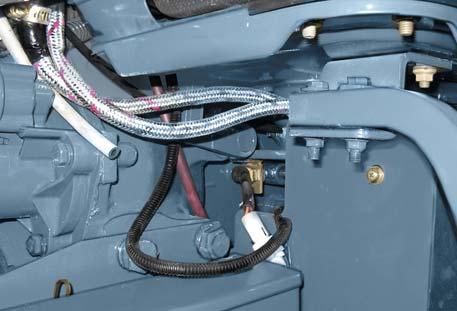
1.To remove the switch, first remove the battery cable from its negative terminal & then remove battery cable from positive terminal.
2.Disconnect wiring harness from neutral switch.
3.Loosen the nut holding the switch to the bracket and remove the switch.
NOTE: After removal of the switch preserve the shims.
Refitment of Neutral Safety Switch
1.Position forward/ reverse lever in neutral position.
2.Refit the switch by using removed shims. For new switch add / remove shims, so that the tractor starts in neutral position only.
3.After ensuring startability in neutral position, tighten all hardwares to complete the assembly.
NOTE: Incase forward / reverse pivot is removed during any repairs; first reassemble the forward / reverse pivot on transmission shaft. Reconnect the forward / reverse cable with pin, cotter pin and washer. Place the forward / reverse in neutral position. Refit the switch by adding / removing shims, so that the tractor starts in neutral position only. After ensuring startability in neutral position, tighten all hardwares to complete the assembly.
When front isolator bracket LH is to be fitted, setting of neutral switch is to be carried out after bracket fitment as per "Refitment of Neutral Safety Switch" mentioned above.
CHAPTER - 1
Tractor Model
5035
/ 3535 SPECIFICATION
Engine Model5035 / 45354035 / 3535 GENERAL
Number of cylinder43 Bore (mm)88.988.9
Stroke (mm)101.6101.6
Displacement (cc)25201892
Compression ratio19.5:119.5:1
Compression pressure (Bar)35-3835-38 at 350 Engine rev/min
Firing order1-3-4-21-3-2
Max. Rated Horse Power (H.P. @ 2800)(5035-49.5, 4535-45)(4035-40, 3535-35)
Max. Torque @ rpm (Nm)145@1900~2100 (5035)116@1900~2100 (4035) 131@1900~2100 (4535)102@1900~2100 (3535)
ENGINE SPEED (rpm)
Rated rpm28002800
High idle2975±502975±50
Low idle1000±501000±50
Injection Nozzle Opening Pressure3510 - 3742 PSI3510 - 3742 PSI
FUEL DieselDiesel
Parts Description5035 / 4535 / 4035 / 3535
MANIFOLDS, CYLINDER HEAD & VALVES
VALVE TAPPETS
Diameter (mm)14.224 / 13.97
Running clearance (mm)0.013 / 0.076
VALVE PUSH RODS
Diameter (mm)Ø9.530D x 1.9 THK Hollow Push Rods
Length (mm)248.3
VALVE TIMING
Inlet opens 9º bTDC ± 2º
Inlet closes35º aBDC ± 2º
Exhaust opens46º bBDC / 42º bBDC
Exhaust closes10º aTDC ± 2º
CONNECTING RODS, PISTONS AND CYLINDER SLEEVES
CONNECTING RODS
MaterialEN - 16C / S48C
Bearing (big end) typeReplaceable Steel Backed Bimetal
MaterialSteel Backed Overlay Plated
Small end (bearings)Replaced
TypeBush
MaterialCu-Lead
Small end bush dia. (mm)Ø30.950 / Ø30.975
PISTON RINGS
Number of rings per piston3
TypeCam Ground Oval
TopKeystone, CKS Plated
MiddleTaper faced
BottomChromium Plated Conformable Oil Ring
Width (Axial) (mm)
Top2.568 / 2.607
Middle2.47 / 2.495
Bottom3.97 / 3.995
Ring Gap (mm)
Top0.25 to 0.45
Middle0.70 / 0.95
Bottom0.25 / 0.50
PISTON Type
MaterialAluminium Alloy
Graded (gms) Weight difference should not be more than 5gms.
±
Piston pin bore (mm)28.003 / 28.009
Number of ring grooves3
Width of ring groove
Top groove(3) Reference Value
Middle groove2.550 / 2.570
Bottom groove4.020 / 4.040
Clearance in grooves
Middle groove0.055 / 0.100
Bottom groove0.025 / 0.070
PISTON PINS
Diameter (mm)Ø27.995 / Ø28
Clearance in piston (mm)0.014 / 0.003 Length (mm)66.5 / 67
CYLINDER SLEEVES TypeWet Liners
Sleeve O.D (mm)98.8 / 99 Sleeve I.D (mm)88.9 / 88.92
Flange stand out / liner protrusion (mm)0.051 above face to 0.025 below face.
Flange width (mm)5.715 / 5.705 (for spare)
Monochrome cast iron
Bearing journal diameter (mm)
Front46.787 / 46.761
Centre46.025 / 45.999
Rear38.1 / 37.846
Running clearance (mm) 0.089 / 0.038
Exhaust cam lift6.325
Inlet cam lift6.274
TIMING GEARS
Number of teeth
Crankshaft gear33
Cam shaft gear66
Injection pump gear66
Idler gear46
Tandem pump gear
Backlash between any pair of gear (mm)0.23 / 0.132
Idler gear end clearance (mm)0.127 - 0.254
Idler gear end float (mm)0.127 - 0.254
CRANKSHAFT
MaterialEN25FQ or EN29B
Main journal diameter (mm)Ø53.99 / Ø54.02
Running clearance main journal (mm)0.076 / 0.018
Crank pin diameter (mm)Ø53.97 / Ø53.99
End clearance (Float) (mm)0.203 / 0.102
Slide clearance main journal (mm)0.203 / 0.102
Running clearance crank pin (mm)0.076 / 0.025
Rear end oil seal dia (mm)91.999
MAIN BEARINGS
Type Replaceable, Shell MaterialSteel backed babbit
TORQUE LOADING (TIGHTENING TORQUE) CHART
DescriptionTorque (Lbs-Ft)
Crankcase Sub-assembly
Pipe Plug1/4'’ For Main Oil Gallery16 to 20
Pipe Plug1/8'’ For Main Oil Gallery8 to 10
Crankcase Water Drain Plug 1/4" (G 6.3mm)14 to 16
Back Plate To Crankcase Mounting Bolt M6x126 to 8
Spin-on Filter Adapter
Adapter Oil Level Gauge
20 to 25
18 to 22
Water Pump Mounting Stud 3/8'’ UNC12 to 14
Front Plate Assembly
Crankcase Front Plate Mounting Bolt G 7.938mm X 19.05 mm18 to 22
Crankcase Front Plate Mounting Bolt 1/4" UNC X 3/48 to 12
Crankcase Front Plate Mounting Screw4 to 6
TORQUE LOADING (TIGHTENING TORQUE) CHART
to 22
Alternator Mounting Bracket on Front Cover To Crankcase Bolt G7.938x63.518 to 22
Alternator To Alternator Mounting Bracket on Front Cover (M8x1.25x85mm)18 to 22
Alternator To Brace Bracket bolt M10x1.5x25mm20 to 25
Alternator With Bracket M10x1.5x85mm35 to 37
Timing Mark Pointer On Front Cover4 to 6
IPG Cover Bolt 12 to 16
Fan Drive Pulley To Crankshaft Mounting Bolt120 to 140
Water Pump Mounting Nut 3/8'’ UNC25 to 30
Alternator Brace Bracket To Cylinder Head (M8x30 mm)18 to 22
Alternator Brace Bracket To Alternator with Belt Guard Nut (M10)18 to 22
Heat Shield Nut With Alternator Mounting Bolt
Heat Shield Bolt Nut M10x1.525 to 30
Tube Thermostat Bypass 8 to 10
Oil Sump & Adapter Plate Fitment
Lubricating Oil Pump To Crankcase 3/8" UNC X 1-1/825 to 30
TORQUE LOADING (TIGHTENING TORQUE) CHART
UNC Long60 to 65
Rocker Arm Mounting Nut M10 x 1.525 to 30
Injector Spill Pipe Banjo M64 to 6
Air Intake Manifold Mounting Bolt M8 x 1.25 x 4518 to 22
Heater For Cold Start M22 x 1.518 to 22
Tube Oil Level Gauge 12 to 15
Exhaust Manifold Sub-assembly
Exhaust Manifold M10 x 1.5 x 4525 to 30
High Pressure Pipes, Low Pressure Pipes
FIP High Pressure Pipe Nut Pump End M12 x 1.517 to 20
FIP High Pressure Pipe Nut Injector End 14 x 1.518 to 22
Clamps For High Pressure Pipes M62 to 4
Fuel Filter Mounting nut Flanged M8x1.2518 to 22
Fuel Pipe Banjo Bolt M12 -on Pump Inlet12 to 15
Fuel Pipe Banjo Bolts M1418 to 22
Flywheel To Crankshaft Mounting bolt 7/16" UNF60 to 70
Spin-on Lub Oil Filter 8 to 12
Valve Housing Cover Nut M10x1.5 mm8 to 10
Hose Clip For FIP Overflow Pipe2 to 4
Bolt Banjo M8 X1, Spill Over & Overflow Pipe12 to 15
Cross Section of Engine (side view)
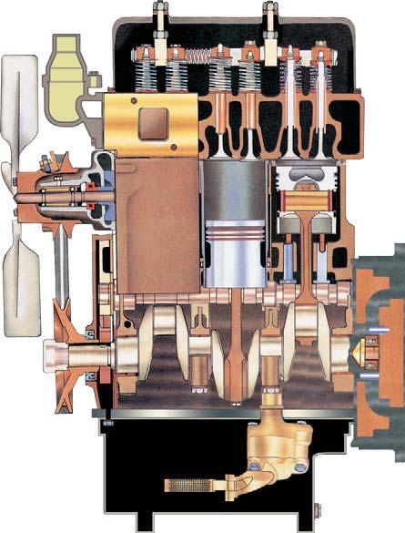
1)Thermostat, opens at 82 0C (167 0F) and allows coolant to circulate. Not repairable, replace if not functioning properly.
2)Valve Rocker arm shaft, diam. rocker arm 19 mm (¾”) drilled oil passage through valve lever shaft center bracket and valve rocker arm shaft to valve rocker arms.
3)Intake valve.
4)Valve guides, for intake and exhaust valves.
5)Exhaust valve.
6)Cylinder sleeves, and pistons are factory mated.
7)Cylinder sleeve packing ring, replace when removing cylinder sleeves. Thoroughly clean grooves and apply some soft soap or soap solution when installing new rings.
8)Flywheel, assembled with six bolts. When flywheel reassembled retorque again.
9)Crankshaft rear oil seal, install carefully in accordance with special instructions otherwise oil leakage will result.
10)Crankshaft rear bearing, takes end thrust.
11)Flywheel ring gear, replaceable.
NOTE: In overall Engine Section, 3 cylinder pictures shown.
12)Floating screen for oil pump, before installing thoroughly wash in gasoline.
13)Crankshaft, four bearings.
14)Crankshaft pinion, 33 teeth, when installing be sure mark lines up with mark on camshaft gear.
15)Crankshaft front oil seal, when installing apply a mixture of heavy oil and graphite to the sealing lip.
16)Camshaft drive gear, 66 teeth, removable.
17)Idler gear, when installing be sure that marks line up with those on crankshaft gear and injection pump gear.
18)V-Belt, for alternator pulley, water pump pulley & main drive crank pulley.
19)Injection pump drive gear, 66 teeth, adjustable hub.
20)Water pump, fan belt driven, permanent packings.
21)Oil pump, fitted on the crankcase with bolt.
22)Connecting rod, when installing apply engine oil and see that the number mark at pump side.
A.GENERAL
Mahindra 35 Series Tractors have 3 & 4 cylinder direct injection water cooled diesel engines with rotary fuel injection pumps and overhead valves. These engines have superior specific fuel consumption and meet US Tier-IV < 50 Hp emission norms.
B. CONSTRUCTION
i)Cylinder
Block
The block is reinforced with ribs so it easily acts as part of the frame connecting the front axle (semi-chassis) and clutch housing.
The engine block is the main body of the engine, around which the engine is built. It is a one piece casting and webs integral with it form the upper halves of the main bearing supports. The lower half bearing supports are in the form of caps machined to mate with the webs in the crankcase.
The crankshaft is supported in 5 & 4 main bearings for 4 & 3 cylinders engine respectively with end thrust on the rear. The bearings are of the steel backed insert type and do not require fitting on assembly. The bearing caps, which hold the lower bearing inserts in position, are not interchangeable and each one is stamped with its location in the crankcase. No.1 is at the front.
During manufacture main bearing caps are rough machined, then assembled to the crankcase prior to being line reamed. This results in each bearing cap being fitted for only one position, therefore, finished bearing caps cannot be supplied individually for service due to the necessity for line reaming to fit the particular bore where it is intended to mate.
The crankshaft supports the connecting rods and pistons along its length and converts the reciprocating movement of the pistons into the rotary movement required to drive the transmission. At the front end of the crankshaft is the gear which drives the timing gear train and the pulley which drives the fan and water pump. The flywheel is mounted on the rear of the crankshaft and to this is mounted the clutch which forms the link between the engine and transmission. The purpose of the flywheel is to oppose and moderate, by its inertia, any fluctuation in the speed of the engine. It counteracts varying torques during the stroke of the engine and provides a rotating balance weight which carries the crankshaft over dead centres. The flywheel is secured to the crankshaft by six bolts. Dowels are provided in the crankshaft flange for accurate location. The starting ring gear is a shrink fit on the flywheel and is replaceable. The cylinder sleeves are replaceable wet type with cooling water running around them. ii)Crankshaft iii)Camshaft
The cooling water is sealed in the Crankcase water jackets with the help of two ‘O’ Rings at the lower end. The top end of the water jacket is sealed when the head gasket is installed and pressed between the head and the sleeve collar.
Sleeves can be obtained as individual items or with graded crankcase.
Never let cylinder sleeve fall this may cause out of round with subsequent scoring, or in extreme cause seizure of the piston.
The Crankshaft is forged from Alloy Steel with Bearing Journals and Pins induction hardened for increased strength and wearing properties. The main journals are supported in Steel Backed Alloy Bearing Shells.
The end thrust or end float of the Crankshaft is controlled at the last rear main bearing having a collared shell.
NOTE: All Crankshafts are dynamically balanced in the factory and do not carry any additional balancing weights.
The Camshaft is made of special cast iron and is supported in babbit lined bearings. Thrust is taken on the locating plate mounted between the camshaft front journal and the driving gear. The drive for the camshaft is taken from the crankshaft gear.
iv)Pistons
The Aluminium Alloy Pistons are cam ground and are fitted with two compression rings and one conformable oil control ring. The have a cavity in the piston crown itself to make a combustion chamber.
The fully floating piston pins are held in place by Circlips at both ends.
Each piston is filled with two compression rings made of cast iron. The top ring is chrome plated. There is one oil control ring. The purpose of oil control ring is to provide an even circulation of lubricating oil giving all over lubrication and cooling action for the piston and sleeves. Excess oil is wiped down to the sump by the lands of the ring.
v)Connecting rod
The I section connecting rods are forged steel and carry a bronze bush at the small end for installation of the piston pins. The big end is mounted on the crankshaft over steel backed alloy replaceable bearing inserts. The big end bearing caps for each connecting rod are matched fit and the matching parts are numbered to ensure correct assembly.
vi) Flywheel is mounted on the rear of the crankshaft secured by six bolts. The replaceable ring gear is shrink fit on the fly wheel.
vii)Lubrication System
Lubricating oils is stored in the engine oil pan bolted to the bottom of the crankcase. Oil is sucked through a fine mesh screen and pick-up tube into the inlet of a 4 lobe internal gear pump. The pump is driven by a gear on the camshaft. The pump has a build in relief valve to limit maximum pressure. Oil is forced from the pump through the filter into the engine lubrication passages. The filter has a bypass valve designed to prevent loss of lubricating oil flow if the filter becomes stagged. Oil from the filter enters the crankcase main oil gallery. A drilling carried oil flow it to the idler drive gear on the front of the engine to lubricate the gear bearing and provide oil flow necessary to splash lubricate the other gears, then drilling carry oil to each camshaft bearing and crankshaft bearing. The number two camshaft bearing journal has a slot cut in it to provide metered oil flow to the valve rocker arm shaft. When the slot is aligned with the drilling from the main oil gallery and the drilling to the valve rocker arm shaft to metered amount of oil is forced to the shaft. Each crankshaft main journal is drilled to the rod journals and the main bearing links have circumferential grooves to provide continuous oil flow to each rod bearing. The rods are designed with side clearance to provide oil flow necessary to splash lubricate the connecting rod small end (wrist) pin bearing and the cylinder walls.
viii)Cooling System
Coolant is circulated through passages located in the crankcase and the cylinder head, by a centrifugal pump mounted in the front of the crankcase. The drive for the water pump is taken from the crankshaft by a belt and pulley system. A thermostat situated in the water outlet ensures that the coolant is not circulated until it has reached the efficient operating temperature.
For complete details refer service manual.
ix)Fuel System
The fuel system consists of fuel lines, fuel filter, fuel injection pump, high pressure pipes, and the fuel injection nozzles. The fuel injection pump is controlled by a Mechanical Governor, which governs the engine speed from idling to full load. For complete detailed servicing information on diesel fuel system components, refer to the fuel injection system service manual.
1.ENGINE
1a.Removal :
1.Raise the hood.
2.Disconnect the battery earth cable before disconnecting any electrical system.
3.Unclip the main cable harness from the bottom of the radiator.
4.Disconnect head lamp and horn cable.

5.Remove the hood pivot bolts and remove the hood.
6.Drain the radiator and crankcase.
7.Disconnect the radiator brace and fan shroud from radiator.
8.Loose and hose clips and remove inlet and outlet hose pipes of the radiator.
9.Remove the two nuts from the bolts securing the radiator to the front axle support. Lift the radiator and rubber pads off. Place the wooden block between axle and axle support prevent tilting.
10.Lock the brakes and securely block the rear wheels.
11.Disconnect the drag link. If power steering is fitted, disconnect the power steering oil pipes (two) at starter side.
12.Support the front of the tractor to take most of the weight off the front tires. Unbolt the radius arm bracket fit from the clutch housing.
13.Remove the front support securing cap screws from both sides. Raise tractor engine until crank shaft pulley will clear support then roll out front axle support with front axle and tires.
14.Disconnect the generator /alternator leads, the oil pressure pipe, and release the harness from the securing clips situated around the front of the engine.
15.Disconnect the starter motor supply cable, solenoid wire and main harness feed wire from the starter (1-1).
16.Disconnect the high and low pressure pipes at the Hydraulic pump removing two socket head (if power steering fitted. Remove dual pump socket) cap screws on each connection.
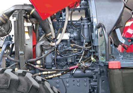
17.Remove the temperature transmitter from the head.
18.Remove the fuel feed pipe from fuel injection pump and close the fuel-shut-off tap and disconnect fuel supply line.
19.Remove the cap screws and lock washer securing the flywheel dust cover.
20.Sling the engine securely and with a suitable hoist tension the ling.
21.Remove the 7 cap screws and attaching the engine to the clutch housing.
22.Ease the engine away from the clutch housing as explained below. Take care that the transmission drive shaft is withdrawn squarely from the pilot bearing and clutch assembly.
23.Use MST-H3-MP-070 special service tool for removal of engine (Fig-3) as follows :
•Keep the rail under the tractor (Fig-4).

•Place jack & support of engine below oil sump.
•Place mini jacks between front axle & front axle support & lock to avoid swinging of engine.
•Place transmission jack below transmission case rectangular part.
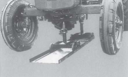
•Raise the jacks till they bear the load.
24.Remove all connections to the engine with clutch housing and vertical loads as described earlier.
25.Take care that the transmission drive shaft is withdrawn squarely from the pilot bearing and clutch assembly.
2C.INSTALLATION OF ENGINE :
1.Install the clutch driven disc by passing aligning tool through the drive member and insert spigot end into the pilot bearing. Place the “flywheel” side toward the flywheel.
2.Place the drive disc (flywheel side mark toward the flywheel) and clutch cover assembly over the aligning tool. Line up the dowel holes in the cover over the dowels in the flywheel. Insert the six bolts and lock washer and tighten up evenly. Withdraw the aligning tool.
NOTE: It is recommend that new gaskets and O’Rings be used on installation.
3.Sling the engine securely. Hoist the engine into position in front of the clutch housing and enter the transmission drive shaft into the clutch assembly.
4.Move engine back turning the transmission and P.T.O. drive shaft to engage the splines of the clutch driven members, until the shaft is located in the pilot bearing and the clutch housing is located on the crankcase dowels.
NOTE: When engine is removed from tractor. Chassis for overhauling always take out the starter motor the alternator & the hydraulic pump and send them for testing.
5.Insert, and tighten the attaching bolts.
NOTE: To assist assembly, two longer bolts may be used to guide and to draw the engine upto the clutch housing.
6.Installation is now the reversal of the removal procedure by using new parts with kit.
7.Fill the cooling system and check the air cleaner oil, engine oil, hydraulic oil, fuel and then bleed the diesel fuel system.


