3 minute read
Cooling System


8.TROUBLE SHOOTING
Troubleprobable Causeremedy
1.Insufficient water1.Acid water, inspect for leaks.
2.Faulty Thermostat2.Test, it necessary, replace.
3.Dirty Water3.Drain & clean system.
4.Defective Connections.4.Replace swollen, worn or loose hose connections.
DEFECTIVE5.Radiator Defective5.Repair. If necessary, replace.
COOLING6.Fan Detective6.Inspect Fan. If damaged, replace.
SYSTEM7.Defective Radiator Cap.7.Replace.
8.Defective Water Pump.8.Inspect water pump impeller & shaft. If necessary, replace.
9.Dirty, Scad Coolant passages.9.Clean & flush passages.
10.Radiator Togged.10.Flush out radiator.
11.Fan Roll Slippage.11.Check the tension; replace, it greasy or worn.
CHAPTER - 9
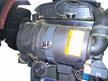
A. AIR CLEANER
All air entering the engine must pass through the aircleaner before entering the inlet manifold and cylinders. To provide an engine with clean and adequate volume of air, is of most Importance. The entire system is so designed that even in extreme dusty conditions and low Engine R.P.M. the engine is not starved of dust free air. In Engine Dry Type Air Cleaner is placed horizontal just infront of radiator.
The curved blades on the periphery of precleaner shield direct the entering air to take a spiral path on entering the body tube due to this motion of air, bigger impurity particles are thrown away rapidly from the body tube and after passing from hopper slot, they fall in the dust collector the precleaned air then passes through paper filter element before entering the engine.
A safety cartridge provided within the boundaries of paper element. This can filter particles upto 120 µ and is of use only in case of any leakage or rupture of paper element and also paper element is removed for cleaning an Air cleaner indicator is provided on dash board it will glow in case the filter element gets jammed.
NOTE: Never remove cartridge when paper elementis removed for cleaning.
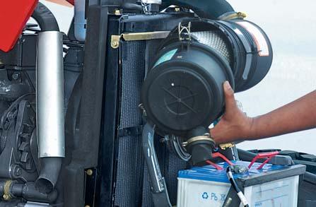
B. REMOVAL & INSTALLATION INSTRUCTIONS
For Air cleaner Replacement Proceed as follows:
1.Open the hood.
2.Loosen the hose clips (A) of hose (B).
3.Loosen the wing nut (C) & turn the clamp (D).
4.Disconnect the Air Cleaner Clog Indicator Sensor wiring connections.
5.Take out air cleaner.
For Air cleaner Servicing Proceed as follows:
6.Open the hood.
7.Check the dust unloader valve (E) and clean if necessary.
8.Turn the clamp (F) of air cleaner.
9.And remove cover (G).
10.Remove Primary Element (H). Remove Secondary Element (Inner Element) ONLY if it is to be replaced. DO NOT attempt to clean Secondary Element.
If Secondary Element is replaced, install new element immediately to prevent dust from entering air intake system.
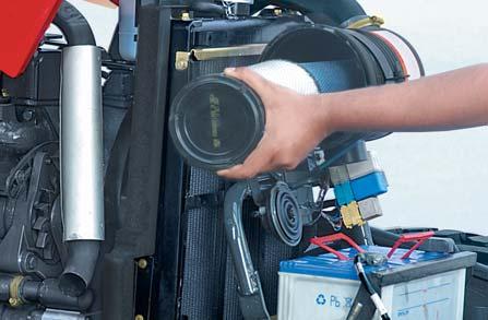


11.Replace Secondary Element (J), if dirty or damaged.


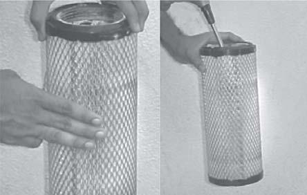
C. Cleaning Primary Element
a.Pat Primary Element with palm of your hand, NOT ON HARD SURFACE.
b.Clean element with compressed air (below 130 kPa or 1.3 Bar). Hold nozzle next to inner surface, and move up and down pleats.
DO NOT direct air against outside of element, as it might force dirt through to inside.
c.Inspect element before reinstalling.
D. Washing Primary Element
DO NOT wash element in fuel oil, oil, gasoline or solvent. DO NOT use compressed air to remove water from element.
E. Inspecting Element
a.Hold a bright light inside element and check carefully for holes. Discard any element which shows the slightest hole.
b.Be sure outer screen is not dented. Vibration would quickly wear a hole in filter.
c.Be sure rubber sealing surfaces are in good condition on both ends. If damaged, replace element.
d.Before you install Primary Element, clean the inside of air cleaner housing & unloader valve with a damp cloth.
e.Ensure that dust unloader valve is facing downward. (With 30 Deg. Vertical axis) f.Install Primary Element & cover and shut bonnet.
F. SERVICE INSTRUCTIONS
1.Check functioning of auto unloader of the dust collector regularly.
2.Paper element of air cleaner should be cleaned with compressed air every 300 hrs. or earlier if required.
3.Paper element of air cleaner should be replaced after every 2 cleanings or 900 hrs. or even earlier if required. Refer Routine Service Schedule Chart.
4.Safety Cartridge should be replaced after every 900 hrs. or earlier if required.
G. STORING ELEMENT
If element is not installed on tractor, seal element in a plastic bag and store in its original shipping container to protect against dust and damage.
G. AIR CLEANER SERVICE INDICATOR
It is fitted on air cleaner outlet connecting to air intake manifold. This is a mechanical type indicator set to 80 milli-bar vacuum in intake system. The red band will be visible in the transparent cover, when the 80 millibar vacuum is reached. At this stage air cleaner has to be cleaned / Serviced.

After servicing, reset the clog indicator by pressing rubber cap. (As marked in the figure).
Ensure red band will move to the original position after resetting.
CHAPTER - 10
(A)Description
The fuel tank is enclosed below sheetmetal platform and is bolted with side part support. The filler cap incorporates an air vent hole and a gasket.
The tank is rubber mounted on front and which are bolted to the clutch housing. At the rear, the scuttle panel, instrument panel and filler plate are all secured to the tank surrounds. A fuel gauge sender / Tank unit is fitted on the tank for fuel level gauge.
The steering column and governor control rod run through a tube in the fuel tank and are enclosed by the tank surrounds.
(B)Removal
1.Drain the tank completely, through either water drain tap.
2.Disconnect the fuel pipe at the tap or water trap and disconnect the fuel return pipe.
3.Raise the hood, and disconnect the battery.
4.Remove the battery.
5.Remove the scuttle panel and the filler plate.


