6 minute read
DIFFERENTIAL LAYOUT


1.Theory of Operation
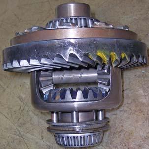
The power from Spline Shaft (1) drive the Gear Crown Wheel (6). This in turn rotate Differential Housing (12). The power from differential housing flows through differential pinion (2) and then to Bevel Gear Differential (5/8). Bevel Gear drives the Bull Pinion (4/11). The Bull Pinion Shaft end matches with Bull Gear (9). This results in rotation of Axle Shaft (10).
The Differential Housing Assembly consists of two Bevel Gear (LH & RH), two pinion and one shaft.
When tractor takes a turn, one axle moves faster than other. This results in rotation of differential pinion to rotate on it’s own axis, and they roll over bevel gear and thus producing differential action.
1.Bolt
2.Bush Bull Pinion Shaft Support
3.Taper Roller Bearing
4.Thrust Washer Bevel Gear
5.Bevel Gear Differential LH
6.Gear Crown Wheel
7.Thrust Washer Bevel Pinion
8.Pinion Differential
9.Differential Case
10.Bevel Gear Differential RH
11.Taper Roller Bearing
12.Coupling
13.Shaft Differential Pinion
14.Pin Spring Differential
15.Lock Plate Bolt Diff. Case
Layout of Differential Assembly
2.Description
The differential is located in the rear housing and is mounted on two taper roller bearings. The drive bevel (ring or crown) gear is bolted to the differential case LH side.
The taper roller bearing is preloaded by shims located between the differential cage and sides of the rear housing, determine the backlash between the bevel gear and the drive pinion and preload on the taper roller bearings support that the differential.
Adjustment of the drive pinion and bevel gear tooth contact is obtain by graded spacer between transmission splined shaft bearing head and machine surface of the housing.
The differential lock unit is incorporated which is controlled by a foot pedal as assembled at the right hand.
The differential gear assembly is a mechanism to provide smooth steering. It automatically provides relative speed to both rear wheels according to road resistance and braking friction at the wheel.
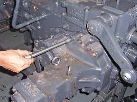
3.Removal of Differential Assembly from Range Section a.Drain oil from the transmission. b.Insert wooden wedges / mini jacks between front axle and axle support to prevent the engine pivoting. c.Remove the rear axle housing. d.Remove the brakes as detailed in “Brakes”. e.Remove hydraulic housing and sheet metal. (If you are working on spline shaft or differential lock). f.Remove LH Rear Axle Carrier. g.Remove retainer (A) alongwith differential housing assembly by loosening bolt (B). h.Tap slightly, o take out the differential assembly (C) complete.
NOTE: Remove differential lock shifting arrangement before dismantling differential case assembly.
4.Cleaning & Inspection
a.Thoroughly clean the inside of the rear housing and blow air.
b.Lubricate all serviceable bearing and wrap in grease proof paper.
c.Remove all gasket material from joint face.
d.Inspect bushes for wear or damage, worn gear, chipped or broken teeth, check splines for burrs and correct fit. All gears should slide easily on spline shaft but no excessive side play. Check sliding couplings and gear for burrs and broken teeth and worn out.
e.Check the shifter rails and forks for straightness, wear of poppet recesses and freedom of movements, grooves for damage.
f.Replace all not serviceable parts with new.
NOTE: Use new oil seals, ‘O’ ring and poppet springs.
5.Dismantling of Differential Assembly
a.Place the Differential in bench-vice.
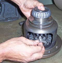
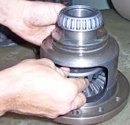
b.Remove the taper roller bearing (A) and withdraw differential lock coupling (B).
c.Remove Ring Gear (C) by loosening bolts (D).
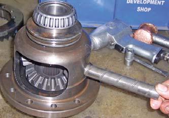
d.Remove spring pin (E) by using Special Tool (F).
e.Push out Differential Pinion Shaft (G).
f.Remove Pinion Differential (H) and thrust washer.
g.Remove Bevel Gear (I) and thrust washer.
6.Cleaning & Inspection
a.Clean all part with suitable solvent. NOTE: Mark the parts to know their original position.
b.Check the differential pinion, thrust bearing and pinion shaft; for excessive wear; pitting or teeth damaged. If these parts are damaged or excessively worn replace as a set.
c.Check bevel gear and thrust washer surface of both bevel gears worn or damaged. Replace the parts.
d.Check the ring gear for wear and damage. If no longer serviceable, replace it with spiral pinion shaft as a set.
e.Check Taper Roller Bearings for wear, pitting or crack. If necessary replace it.
7.Assembly of Differential
a.Place the differential case on the table.
b.Place the thrust washer and bevel pinions inside.
c.Insert the pin (A) in the differential pinions with washer and lock with the pin.
NOTE: Before assembling, all parts should be dipped in transmission oil.
d.Install the pinion gear and thrust washers.
e.Install bevel gears and thrust washers.
f.Install differential pinion shaft and spring pin.
NOTE: Check the gear backlash, if it is not in limit, replace the gears set.
g.Reassemble the ring gear and tighten the bolt as per specified torque and lock the lock washers.
h.Press the taper roller bearing cone on left side.
i.Install differential lock coupling and press taper roller bearing cone of RH side.
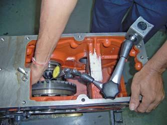
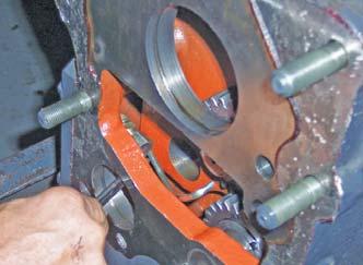
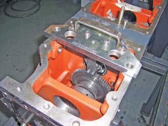
8.Installation of Differential Case Assembly to Transmission a.Install differential assembly in transmission case from LH side cutout and hold. b.Install RH side bearing cup in Transmission-case. c.Locate differential assembly in RH side cup. Install LH side carrier with bearing cup. d.Align and install both side carrier with same shims (as removed). e.Tighten the both carrier securing bolts with specified torque. f.Check the preload of bearings as specified. g.After preloading check the backlash. h.Install rear axle as detailed in “Rear Axle”. i.Install PTO housing assembly. j.Fill the oil.
NOTE: Check preload without spiral gear pinion.
9.Dismantling of Spline Shaft Assembly
a.Remove idler gear assembly and other parts, lubrication pipe (A).
b.Using Special Tool (B), remove Spline Shaft Assembly.
c.Using special tool (B) for locking rotation of spline shaft remove two lock nuts of spline shaft end.
d.Remove gear 4WD input.
e.Slowly tap spline shaft from lock nut end and remove from rear side.
f.Remove all gears of spline shaft assembly.
g.Remove 4WD shifting assembly and 4WD output shaft assembly.
10.Assembly of Spline Shaft
NOTE:Spline-shaft preloading to be done after installing all Range Driven Gears.
1.Install taper roller bearing cone with spline shaft.
2.Insert spline shaft from transmission-case rear side.
3.Insert all gear, bearing, spacers, Spline collar as shown in section. (For correct preloading use graded spacer between front taper roller bearing and bush).
4.Install front taper roller bearing and tighten the spline shaft assembly with lock nut to specified tightening torque. Check the preload with string and spring balance.
5.Adjust graded spacer if required to achieve specified bearing preload.
11.ADJUSTMENTS
a.PRELOADING OF DIFFERENTIAL CASE BEARING
The Ring Gear (Crown Gear) and spline shaft are serviced in matched set and should only be fitted after preloading.
In order to ensure quiet operation and long life of ring gear and spline shaft set the following assembly and adjustment procedure should be rightly followed.
•Check the spline shaft and ring gear are a matched set. (Number) b.BACKLASH AND TOOTH CONTACT BETWEEN RING GEAR AND SPLINE SHAFT.
•Preload the differential case bearings.
1)Assemble the differential case and carrier bearings with left and right shims same as before dismantling. Tighten with specified torque and check the preload as follows.
2)Loop both ends of a piece of string and slip on loop round the differential case opening. Then Wind the string around the differential housing. Secure a spring balance into the free end (as shown in figure) and pull.
NOTE: 1.Pull to keep the assembly revolving at constant speed which should be between 4.4 - 6.6 lbs.
2.Preloading the differential case and spline shaft should be done before assembling of spline shaft.
3.Add or remove shims between the right hand bearing carrier and Transmission Case until the above figure is obtained.

4.Once the correct preload has been obtained, it will only be necessary to transfer shims from one bearing carrier to another to obtain correct backlash between ring gear and spline shaft teeth.
5.After Preloading, remove differential case assembly with shims and fit after preloading the spline shaft.
1)Set the dial indicator between ring gear and Spline Shaft. Move the ring gear by hand.
2)When backlash is more, decrease the number of shims from the ring gear opposite side and insert the removed shims in ring gear side. When the backlash is too less decrease the number of shims from the ring gear side and insert the removed shims in the opposite side.
3)Adjust the backlash properly by repeating the above procedure.
4)Apply red lead / blue light over several teeth at three positions equally spaced on the ring gear.
5)Turn the ring gear, and spline shaft while pressing a wooden piece against the periphery of the ring gear.
6)Check the contact if not proper according to the instructions below.
More than 35% red lead contact are on the gear tooth surface.
The center of both contact a 1/3 of the entire width from the small end.
Adjusting with thicker shims to move spline shaft backward and place the RH shim to left to move ring gear left ward.
Repeat above until proper tooth contact and backlash are achieved.
Fig. A & B gives view of correct markings.
Fig. C & D gives view of setting too far in. This gives incorrect tooth contact resulting noisy operation and premature wear of gears.
Fig. E & F shows the markings of a pinion which has been set too far out. This tends to cause premature wear of the bevel gear.
If it is necessary to reset the pinion, the backlash will need to be adjusted.


