2 minute read
& Flywheel


2.Inspect the crankcase for trueness, using the crankshaft as follows : a)Wipe the bearing supports of the crankcase free of oil with a lint free cloth. The crankcase should be bottom side up and levelly supported. b)Install the upper halves of the bearings to the crankcase. If the original bearings are being reinstalled, ensure that they are fitted to the positions from which they were removed. The location nibs of the bearings must fit into the notches in the main bearings supports. c)Smear blueing on the crankshaft main journals and lower it carefully and evenly on to the bearings. Do not install the bearing caps and lower bearings. d)Rotate the crankshaft back and forth through approximately 180 0 , remove the crankshaft evenly and inspect the upper bearing for an even transfer of blueing from the journals to the bearings. e)Fit the capscrews and tighten to the torque detailed in SPECIFICATIONS. Do not rotate the crankshaft. f)Remove the bearing caps and measure the thickness to which the plastigauge has been crushed. This thickness should be as detailed in SPECIFICATIONS. g)If the clearance is excessive, it may be necessary to grind the crankshaft and install undersize bearings. These bearings are available in sets of +0.030” and +0.015”. See para. 3c for details of re-grinding crankshaft.
1)Any bearings that do not show all over even blueing should be replaced by new. It is advisable to replace all bearings by new ones if an original one is faulty.
2)Clean the blueing off the crankshaft and bearings.
3)Checking main bearing running clearance.
4)Install the upper bearing halves.
5)Place the crankshaft in position.
6)Lay a length of plastigauge along the crankshaft journals.
7)Fit the bearing lower halves to the bearing caps and assemble the caps to the crankcase.
4.Check the crankshaft end float a)Assemble the crankshaft with the main bearings in position. b)Lever the crankshaft towards the front of the engine so that the thrust face is tight against the rear thrust flange of the rear main bearing.
NOTE: Bearing cap bolts should be slackened off slightly to facilitate this operation.
If the clearance is excessive the rear main bearings must be replaced.
D.THE CRANKSHAFT
1.Examine the journals for excessive scoring.
2.Measure the diameter of each journal at various points to check any out of round tendencies. If the journals are excessively worn it will be necessary to re-grind the crankshaft and fit undersize bearings. Limits for undersize grinding are given in fig. 7.
NOTE: Maximum allowable taper on crank pins and journals is 0.00015” per inch of length. Crank pins and journals must be polished and must not be more than 0.00015” out of round. Run-out on centre main bearing journals must not exceed 0.0008”, total indicator reading with the shaft mounted on V blocks at the front and rear journals.
3.Examine the clutch shaft pilot bearing for excessive wear or corrosion. If necessary pull the bearing from the crankshaft and replace with new.
4.Examine the flywheel dowels for wear and looseness of fit. If necessary press in new dowels to the dimensions shown in fig.5.
5. Ensure that the oil ways in the crankshaft are clear.
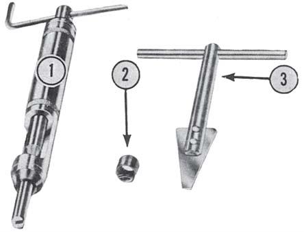
1.REMOVAL a)Place the special tool (3-6) into the insert and turn in an anti-clockwise direction. Never reuse an insert which has been removed.
2.INSTALLATION a)Fit a new insert (2-6) into the driver (1-6) with the driving lug to the bottom. b)Screw the insert into the tool guide until it is flush with the end of the tool. c)Place the inserting tool over the tapped hole in the crankcase and turn the handle in a clockwise direction until the insert leaves the tool. Care must be taken not to drive the insert in too deeply (refer to SPECIFICATIONS).
6.MUST BE CONCENTRIC WITHIN
7.These holes must be clean and free of chips and burrs after grinding. Remove sharp edges.
Permissible width of all Main Journal and Crank Pins except at No. 5 Journal ‘C’ listed above.


