1 minute read
Crankcase, Crankshaft, Main Bearings & Flywheel


E -Place FIP mounting Gasket on machined face of the Adapter plate
F -Place Rotary fuel injection Pump on FIP Mounting studs located on crankcase. Slide the FIP drive shaft into FIP Gear by matching its Keyway.
Scenario - II : Engine is fitted on Tractor and Crankshaft is NOT rotated while FIP is in removed condition.
Follow steps C, D, E & F
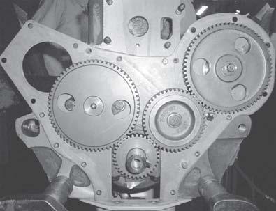
Scenario - III : Engine is being overhauled in shopfloor and timing cover is in removed condition. Achieve positions of Markings on gears as depicted in Fig.A.
Follow steps C, D, E & F
G -Tighten the mounting Nuts to hand tight limits, H -Tighten FIP gear mounting nut with specified Torque of 55-65 Lb. ft.
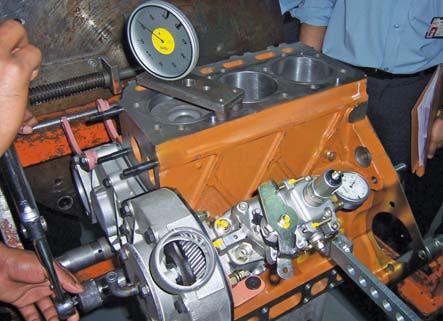
K -Fix a dial indicator in Special Tool ensuring that the needle of Dial Gauge rests on NEEDLE of special tool with some PRE LOAD.
L -Further fix the assembly of dial indicator with Special Tool on the FIP camshaft (near a distributor) with the help of Nut provided at the center ensuring that the needle rests on PLUNGER of FIP as depicted in Fig.B.
M -Set the Dial to ZERO
N -Move the Rotary FIP towards or away from the Engine along the FIP mounting Studs till the Dial reads 0.95 ± 0.02 mm for 4035/3535, 1.0 ± 0.02 mm for 4535/5035. The Slot on FIP flange will permit such movement of FIP along the studs.
O -Torque the FIP mounting nuts to 18.44 ± 2.21 Lb. ft.
Assembly procedure for Heater Plug by Turn From Finger Tight Method (TFFT)
The proper method of assembling NPT threaded connectors is to assemble them finger tight and then wrench tighten further to the specified number of turns from finger tight (T.F.F.T.) given in Table A. The assembly procedure given below is recommended to minimize the risk of leakage and/or damage to components.
1.Inspect port and connectors to ensure that threads on both are free of dirt, burrs and excessive nicks.


