Mahindra Tractor '35' Series 4WD 3535 4035 4535 5035 Gear Service Manual

Page 91

Connecting Rods, Pistons & Cylinder Sleeves 4.

ASSEMBLY :

a)

Push the piston pin into boss of the piston.

b)

Position the connecting rod inside the piston and align the bushing with the piston pin. During the assembly of the piston and the connecting rod, ensure that the combustion cavity in the piston is towards the F. I. Pump side.

c)

Before installing sleeve, check that the counterbore at the top and sealing ring groove at the bottom are clean and free from foreign material. All sleeves should enter crankcase bores full depth and should free to rotate by hand. (without sealing ring)

NOTE:

The cylinder head gasket forms the upper cylinder sleeve seal, and excessive sleeve standout will result in coolant leakage. To test lower sealing rings for proper installation, fill crankcase water jacket with cold water and check for leaks near bottom of sleeves.

d)

Push the piston pin into the other boss and install the circlips on both sides of the piston securely. The piston pin can be pushed with slight hand pressure.

e)

Using piston ring expander fit the rings to the piston starting the bottom ring and working up.

Fig. 5

NOTE:

Multi-piece oil control rings should be fitted to the top oil control groove. The expander (1-8) must be installed first, followed by the two flat rings (2-8) either side of the expander. The gaps in the flat rings must be at 1800 to each other.

Piston Rings Check piston ring gap using a feeler gauge. Connecting Rod Alignment

NOTE:

To check piston ring gap the ring must be placed squarely in a new cylinder sleeve (Fig. 7). Replace piston ring as a set only.

Piston Clearance to Cylinder Sleeve Check the piston clearance in the sleeves using a 0.10 mm (0.004 inch) ribbon gauge 12 mm (0.005 inch) wide with a tension scale Fig.10 in the following manner; a)

Position the ribbon in the cylinder bore so that it extends the entire length of the piston, 90 degrees from the piston pin location.

b)

Invert the piston and install it in the bore so that the end of the piston is about 38 mm (1.5 inch) below the top of the cylinder block and the piston pin is parallel to the crankshaft axis.

c)

Hold the piston and slowly pull the scale in a straight line with the ribbon, noting the pull required to remove the feeler ribbon. Do not bend or kink the ribbon gauge.

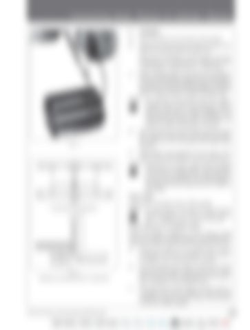
Fig. 6 Checking connecting rods for squareness

35 Series 4WD, Model - 3535, 4035, 4535 and 5035 SM June’08

C-35


Turn static files into dynamic content formats.

Create a flipbook

Articles inside

Hydraulics

1min
pages 355-356

Hydraulics

1min
page 354

Hydraulics

1min
page 353

Hydraulics

1min
pages 348-352

Hydraulics

1min
pages 346-347

Hydraulics

1min
pages 344-345

Hydraulics

10min
pages 326-341

5. HOW THE INTERNAL LEVERAGE SYSTEM FUNCTIONS

1min
page 325

4. FUNCTIONING OF FLOW CONTROL VALVE

3min
pages 322-324

Steering

5min
pages 312-315, 319, 321

Steering

1min
pages 310-311

Electrical System

13min
pages 294-295, 299-309

Electrical System

1min
page 293

Electrical System

1min
page 291

Electrical System

2min
page 290

Electrical System

1min
pages 288-289

Electrical System

1min
page 287

Electrical System

1min
page 286

Electrical System

1min
page 283

Electrical System

1min
pages 280-281

Electrical System

1min
pages 278-279

Brakes

2min
pages 239-242, 246

Differential Lock System

1min
pages 225-226, 228, 230, 232

Differential

1min
pages 220-222

Differential

2min
pages 219-220

DIFFERENTIAL LAYOUT

6min
pages 210-218

Fuel System

17min
pages 159, 170-177, 180, 182-183, 185-200

Fuel System

1min
page 158

Fuel System

1min
page 157

Fuel System

3min
pages 153-155

Fuel System

1min
pages 152-153

Fuel System

1min
page 151

Cooling System

3min
pages 142-143, 145-149, 151

Cooling System

2min
pages 140-141

Cooling System

2min
page 139

Cooling System

1min
page 138

Cooling System

1min
page 137

Cooling System

1min
pages 136-137

SPECIAL NOTES & TROUBLE SHOOTING

2min
page 127

Crankcase, Crankshaft, Main Bearings & Flywheel

1min
pages 123, 125

Crankcase, Crankshaft, Main Bearings & Flywheel

1min
page 122

Crankcase, Crankshaft, Main Bearings & Flywheel

1min
page 121

Crankcase, Crankshaft, Main Bearings & Flywheel

1min
page 120

Crankcase, Crankshaft, Main Bearings & Flywheel

2min
page 119

Crankcase, Crankshaft, Main Bearings & Flywheel

2min
page 118

& Flywheel

2min
pages 116-117

Crankcase, Crankshaft, Main Bearings & Flywheel

1min
page 115

Crankcase, Crankshaft, Main Bearings & Flywheel

1min
page 114

Crankcase, Crankshaft, Main Bearings & Flywheel

1min
page 113

Timing Gear Train, Front Cover & Camshaft

1min
pages 109, 111

Timing Gear Train, Front Cover & Camshaft

1min
page 108

Timing Gear Train, Front Cover & Camshaft

2min
pages 106-107

Timing Gear Train, Front Cover & Camshaft

1min
page 105

Lubrication Systems

1min
pages 100-101, 103

Lubrication Systems

1min
page 99

Connecting Rods, Pistons & Cylinder Sleeves

1min
pages 95, 97

Connecting Rods, Pistons & Cylinder Sleeves

1min
page 94

Connecting Rods, Pistons & Cylinder Sleeves

1min
page 93

Connecting Rods, Pistons & Cylinder Sleeves

1min
page 92

Connecting Rods, Pistons & Cylinder Sleeves

1min
page 91

Connecting Rods, Pistons & Cylinder Sleeves

1min
page 90

Connecting Rods, Pistons & Cylinder Sleeves

1min
page 89

Manifolds, Cylinder Head & Valves

1min
pages 85, 87

Manifolds, Cylinder Head & Valves

2min
page 84

Manifolds, Cylinder Head & Valves

1min
page 83

Manifolds, Cylinder Head & Valves

1min
pages 81-82

Manifolds, Cylinder Head & Valves

1min
page 80

Manifolds, Cylinder Head & Valves

1min
page 79

Manifolds, Cylinder Head & Valves

1min
page 78

Manifolds, Cylinder Head & Valves

1min
page 77

Removal & Refitment of Safety Neutral Switch

13min
pages 56, 59, 61-68, 70-73, 75

Removal & Refitment of Hydraulic & Transmission Suction Oil Filter

1min
page 55

Removal & Refitment of Flooring and Linkages

1min
page 53

Removal & Refitment of Instrument Cluster, Scuttle & Steering Column Cover

1min
page 52

Removal & Refitment of Air Cleaner

1min
page 51

Removal & Refitment of Air Cleaner

1min
page 49

Removal & Refitment of Alternator

1min
page 48

Removal & Refitment of Alternator

1min
page 47

Removal & Refitment of Fuel Tank

1min
page 44

Removal & Refitment of Fender

1min
page 42

Removal & Refitment of Hood

1min
page 41

Removal & Refitment of ROPS

2min
pages 38-39

Splitting Between Engine & Transmission

1min
page 33

Splitting Between Front Axle & Engine

1min
page 30

Single Parts Repair, Off-Season Inspection or General Overhaul

14min
pages 13-24, 27-29

Safety Notes

6min
pages 8-12

Safety Notes

2min
page 4
Issuu converts static files into: digital portfolios, online yearbooks, online catalogs, digital photo albums and more. Sign up and create your flipbook.
Mahindra Tractor '35' Series 4WD 3535 4035 4535 5035 Gear Service Manual by www.heydownloads.com - Issuu