Manifolds, Cylinder Head & Valves 4b.
DISMANTLING
1)
Remove the four nuts and conical washers securing the injector clamps. Carefully withdraw the injector and copper washers from the cylinder head. Keep the injectors in a clean place free from dirt and dust.
NOTE: 2)
Using a valve spring compressor, compress the valve spring sufficiently to allow removal of the collet (8-5).
3)
Release the pressure then remove the retainer (2-5) and spring (3-5) the valve seat should also be removed.
4)
Remove the valve (2-5) and identify them so that they can be installed in the original positions.
5)
If necessary press out the valve guides from the under side of the head using pusher slightly smaller than the guide to prevent it jamming in the bore.
4c.
CLEANING, INSPECTION & REPAIR
(a)
CLEANING
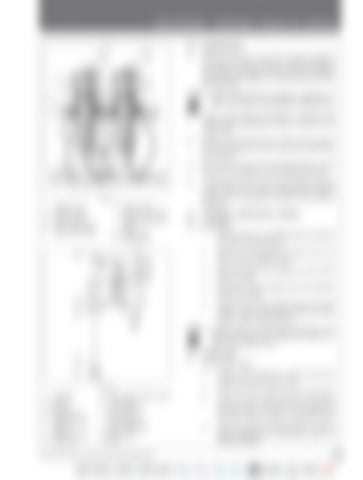
Fig. 5 1. 2. 3. 4. 5.
Intake valve Exhaust valve Valve spring Valve stem guide Valve seat insert
6. Valve spring retainer cup lower 7. Valve spring locks upper 8. Valve stem 9. Coolant jet
Fig. 6 1. 2. 3. 4. 5.
Camshaft Tappet Push rod Cylinder head Adjusting screw locknut 6. Adjusting screw 7. Rocker arm
8. Valve spring retainer upper 9. Valve spring one spring only 10. Valve spring one spring only 11. Valve spring seat 12. Valve guide 13. Valve
35 Series 4WD, Model - 3535, 4035, 4535 and 5035 SM June’08
Before disassembly of injectors, inspection or repair of nozzles, contact BOSCH dealer/service.
1.
Wash all parts in a suitable solvent and blow dry with compressed air.
2.
Remove any old gasket material from the faces of the cylinder head.
3.
Blow through all oil passages to ensure that they are clear.
4.
Remove all carbon deposits from the cylinder head and valves.
5.
Remove any carbon deposits from the valve guides, using a wire brush. Blow out loose carbon with compressed air.
NOTE:
Guides require careful cleaning because any remaining carbon will deflect the pilot of a valve seat refacing tool.
(b)
INSPECTION
1.
The Cylinder Head a.
Inspect the casting for cracks and burnt metal around the valve ports.
b.
Check the valve seats for cracks and pitting.
c.
Position a lamp underneath the valve guides and examine the bore of the guide for burning, cracks or signs of excessive wear.
d.
Check the diameter of the guides at several points against the dimensions given in SPECIFICATIONS. C-25


