Wacker Kramer 2506 Telehandler Service Manual - PDF DOWNLOAD

Page 78

Maintenance and service work 3.11 Replacing the fuel filter Danger!

B

If the fuel, as it drains, comes into contact with hot engine parts or the exhaust system, there is an increased fire hazard!

☞ Never bleed the fuel system if the engine is hot!

Environment!

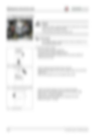
Fig. 38: Fuel filter position

Use a suitable container to collect the fuel as it drains and dispose of it in an environmentally friendly manner!

☞ Change the fuel filter as follows: • • • •

Pinch off fuel feed line B with a suitable tool Thoroughly clean the outside surfaces of fuel filter Slacken and unscrew fuel filter cartridge using a commercially available tool Collect the fuel as it drains

Fig. 39: Unscrewing the fuel filter

• Clean the sealing surface of the filter carrier if it is fouled • Lightly oil the rubber gasket of the new filter cartridge or apply a thin coat of clean diesel fuel to it • Screw on the cartridge by hand until the gasket makes contact

Fig. 40: Cleaning the sealing surface and oiling the gasket

• • • • •

Tighten the fuel filter cartridge by turning it a further half revolution Remove the tool which has been used to pinch off the fuel feed line 38/B Make a test run – and check for tightness! Dispose of the old fuel filter cartridge by an ecologically safe method Bleed the fuel system – see page

Fig. 41: Tightening the fuel filter

3-14

Serv-HB 40702 – Edition 2.0 * 407-02s0322_Wartung.fm


Turn static files into dynamic content formats.

Create a flipbook

Articles inside

Switch with lock (green) – 3rd control circuit lock

1min
page 98

Potentiometer – low-speed control (option

1min
page 97

Switch (grey) – machine lights (low beam and rear lights

1min
page 96

Rotary switch – heater fan (heating, ventilation

1min
page 95

Air conditioning (option) switch (grey

1min
page 93

Hour meter

1min
page 92

Fuel tank gauge

1min
page 91

Cold starter indicator light (yellow

1min
page 90

High beam indicator light (blue

1min
page 89

Indicator light (red) – 3rd control circuit, continuous operation (option)

1min
page 88

Engine oil pressure indicator light (red

1min
page 87

Parking brake indicator light (red

1min
page 86

Alternator charge function indicator light (red

1min
page 85

Diesel engine temperature indicator light (red

1min
page 84

Indicator light (red) – hydraulic oil level

1min
page 83

Right/left turn indicator light (green

1min
page 81

Right/left turn indicator light (green) for rear attachments

1min
page 80

Indicator light (red) – overload cutoff (option

1min
page 79

Indicator light (yellow) – accelerator pedal lock (option

1min
page 78

Differential lock indicator light (green

1min
page 77

Indicator light (yellow) – hose burst valve (comes on if the load sta biliser is switched on)

1min
page 76

Radio aerial (option

1min
page 75

Front wiper

1min
page 74

Switch console – heating, ventilation

2min
page 72

Proportional electronics – additional control circuit (option

1min
page 71

Multifunctional lever – turn indicators, headlights, wipers

1min
page 70

Brake fluid tank

1min
page 69

Washer system tank

1min
page 59

First-aid kit (option) in storage compartment under the seat

1min
page 58

Lock for hinged side window

1min
page 57

Fire extinguisher (option

1min
page 56

Seat

1min
page 54

Switch panel – rear additional control circuits (option

1min
page 49

Rear right working light (option

1min
page 46

Interior light

1min
page 43

Radio loudspeaker (option

1min
page 45

Fuse cover

1min
page 42

Right-hand switch panel – options

1min
page 41

Indicating instrument – indicator lights

1min
page 36

Diagnosis connector (drive

1min
page 40

Board – central electrics (relays, fuses, etc

1min
page 38

Instrument panel – switch panel

1min
page 37

12 V socket

1min
page 35

Air vent – front window

1min
page 34

Front/rear working lights

1min
page 31

Roller sun-visor

1min
page 33

Prepared installation for radio (option

1min
page 32

Rearview mirror for trailer coupling (option

1min
page 29

Wheel chock

1min
page 27

Lock for hinged side window

1min
page 26

Door lock

1min
page 25

Rear hooks for loading/tying down the machine (left/right

1min
page 28

Hydraulic connections 3rd control circuit (additional control circuit as an option

1min
page 24

Hydraulic connections (option) (unpressurised return, leak oil line

1min
page 22

Front-edge protection

1min
page 23

Socket – trailer lights (option

1min
page 20

Trailer coupling (option) Autohitch coupling (option

1min
page 18

Hydraulic connections (additional control circuit, option

1min
page 16

Reflectors (2 x on rear end of machine, 2 x on rear light bracket

1min
page 19

Rear left working light (optionally on the right

1min
page 12

Hydraulic oil tank filler inlet

1min
page 15

Engine cover lock

2min
page 14

Rear hooks for tying down the machine (left/right on the frame

2min
page 17
Issuu converts static files into: digital portfolios, online yearbooks, online catalogs, digital photo albums and more. Sign up and create your flipbook.
Wacker Kramer 2506 Telehandler Service Manual - PDF DOWNLOAD by www.heydownloads.com - Issuu