Cab overview, use, operation 85
84 76
77
78
1.3
86
83
87
79 82
88
81
89 1
80
94
90
93
91 92
95
97
98
99
100
101
96
102
107
109
70
108
112
113
114
115
116
118 119 123
125
1-4
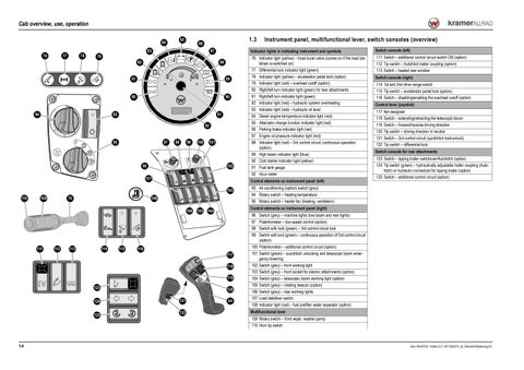
76 Indicator light (yellow) – hose burst valve (comes on if the load stabiliser is switched on) 77 Differential lock indicator light (green) 78 Indicator light (yellow) – accelerator pedal lock (option) 79 Indicator light (red) – overload cutoff (option) 80 Right/left turn indicator light (green) for rear attachments 81 Right/left turn indicator light (green) 82 Indicator light (red) – hydraulic system overheating 83 Indicator light (red) – hydraulic oil level 84 Diesel engine temperature indicator light (red) 85 Alternator charge function indicator light (red) 86 Parking brake indicator light (red) 87 Engine oil pressure indicator light (red) 88 Indicator light (red) – 3rd control circuit, continuous operation (option) 89 High beam indicator light (blue) 90 Cold starter indicator light (yellow) 91 Fuel tank gauge 92 Hour meter
111 Switch – additional control circuit switch ON (option) 112 Tip switch – Autohitch trailer coupling (option) 113 Switch – heated rear window
120 121 122
Switch console (right) 114 1st and 2nd drive range switch 115 Tip switch – accelerator pedal lock (option) 116 Switch – disabling/enabling the overload cutoff (option) Control lever (joystick) 117 118 119 120 121 122
Not assigned Switch – extending/retracting the telescopic boom Switch – forward/reverse driving direction Tip switch – driving direction in neutral Switch – 3rd control circuit (quickhitch lock/unlock) Tip switch – differential lock
Switch console for rear attachments 123 Switch – tipping trailer switchover/Autohitch (option) 124 Tip switch (green) – hydraulically adjustable trailer coupling (Autohitch) or hydraulic connection for tipping trailer (option) 125 Switch – additional control circuit (option)
93 Air conditioning (option) switch (grey) 94 Rotary switch – heating temperature 95 Rotary switch – heater fan (heating, ventilation) 96 97 98 99
117
124
Switch console (left)
Control elements on instrument panel (right)
106 105 104
111
Indicator lights in indicating instrument and symbols
Control elements on instrument panel (left) 103
110
Instrument panel, multifunctional lever, switch consoles (overview)
44
100 101 102 103 104 105 106 107 108
Switch (grey) – machine lights (low beam and rear lights) Potentiometer – low-speed control (option) Switch with lock (green) – 3rd control circuit lock Switch with lock (green) – continuous operation of 3rd control circuit (option) Potentiometer – additional control circuit (option) Switch (green) – quickhitch unlocking and telescopic boom emergency lowering Switch (grey) – front working light Switch (grey) – front socket for electric attachments (option) Switch (grey) – telescopic boom working light (option) Switch (grey) – rotating beacon (option) Switch (grey) – rear working lights Load stabiliser switch Indicator light (red) – fuel prefilter water separator (option)
Multifunctional lever 109 Rotary switch – front wiper, washer pump 110 Horn tip switch
Serv-HB 40702 – Edition 2.0 * 407-02s0310_a3_Übersicht-Bedienung.fm


