Maintenance Mode
Cha pte r C
Cha pte r C
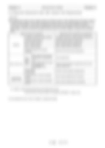
C-5 Required Adjustment after AML System Part Replacement [NOTICE] The adjustment value for each model is stored in the flash memory. When replacing the CPU board, read out the flash memory data from the malfunctioning CPU board to the PC, and write the data to the flash memory of new CPU board again. In that way, the adjustment works other than the clock adjustment become unnecessary. However, always check visually that the numerical value indications, such as boom length and boom angle, as well as the symbol indication that are shown on the AML display unit agree with the actual status. Name of part to be replaced
Detector
AML control unit
Proportional solenoid valve
Adjustment item required to be performed
Outrigger extension length detector
Outrigger extension length detector adjustment
Slewing angle detector
Slewing angle detector adjustment
Boom length detector
Boom length detector adjustment
Boom angle detector
Boom angle detector adjustment
Pressure sensor for moment detection
Moment and load radius adjustment
DISP board CPU board
When data can be read by computer for maintenance 1)
Clock adjustment
When data cannot be read by computer for maintenance 1)
Perform all the detector adjustments and valve output adjustment.
CON1 board CON2 board
Perform all the detector adjustments.
Proportional sol. valve for slewing control
Valve output adjustment for slewing
Proportional sol. valve for elevation control
Valve output adjustment for elevating
1): Refer to "Data Readout/Rewriting with Maintenance Tool" (Can be found in service section of TADANO INTRANET in Japan only) For the adjustment work, refer to Chapter D, Adjustment Mode.
C - 65
W301-0471E


