15 minute read
Maintenance Mode


2.20 Language selection
This is a function to change the displayed language. In the maintenance main menu of Fig. 1.3.1, select "Language," and press the < > key to display the language selection screen shown in Fig. 2.20.1. To go back to the maintenance main menu, press the < > key.
The currently selected language is highlighted enclosed by a square frame. Press the < > key (scroll up) or the < > key (scroll down) to move the highlight to the desired language, and press < > to register the setting.
To go back to the maintenance main menu, press the < > key.
C - 3 Integrated Information Display Screen
This is a screen for checking the current operation status in the maintenance screen or in the a djustment screen.
3.1 Crane Information display screen
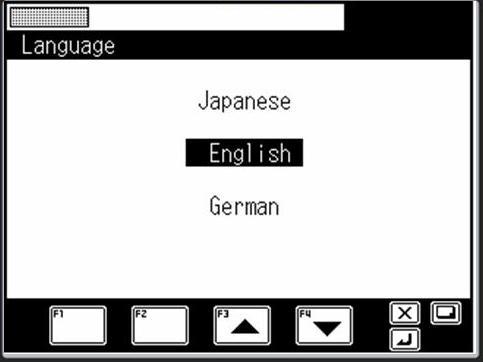
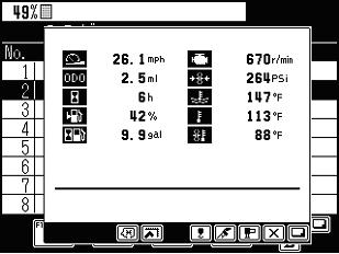
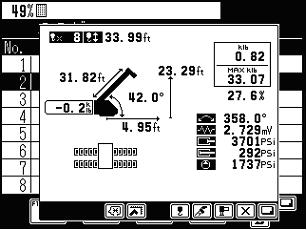
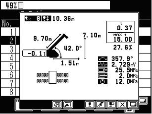
In the maintenance screen and adjustment screen, pressing the < > key displays the integrated information display screen (crane information). Depending on the unit system that is selected, the displayed numerical value changes as shown in Fig. 3.1.1 and Fig. 3.1.2.
3.2 Vehicle Information display screen
When the vehicle information is obtained from the CAN port, pressing the < > key again, while the integrated information screen is being displayed, displays the integrated information display screen (vehicle information). However, the vehicle information is displayed first when PTO is OFF, and pressing the < > key again changes the screen to the crane information. Also, as with the crane information display, the displayed numerical value changes as shown in Fig. 3.2.1 and Fig. 3.2.2 depending on the unit system that is selected.
3.3 Display contents
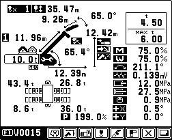
The crane information contents displayed in the integrated information screen are shown in Fig. 3.3.1, and the vehicle information contents are shown in Fig. 3.3.4. For the function specific display (slow stop adjustment, over-front special performance, etc.), refer to the corresponding function specification.
Display contents in this area vary depending on the conditions. Refer to Figs. 3.3.2 for the items which cannot be displayed in this screen.

[1]: Number of part lines
[2]: Hook movement
[3]: Jib length (Displayed only when jib operation is selected)
[4]: Jib angle display (Displayed only when jib operation is selected)
[5]: Boom length
[6]: Boom angle
[7]: Top sheave lift
[8]: Load radius
[9]: Hook load
(Payload + Sling + Hook block)
[10]: Rated lifting capacity = Max. Hook load
[11]: Moment load rated
[12]: Load ratio ( EN13000 spec.)
[13]: Outrigger state display
[14]: Maintenance mode display icon
[15]: Oil temperature 50°C icon
There is no display of 85°C icon.
[16]: Hook-in icon (Only for hook-in specification)
[17]: Tilt cylinder full retraction icon
(Only for SACO-Jib specification)
[18]: Jib lock pin unlock icon
[19]: Boom elevation slow stop cancel icon
[20]: Slewing angle
[21]: Distortion voltage
[22]: Elevating cylinder extension pressure
[23]: Elevating cylinder retraction pressure
[24]: Main pump pressure
[25]: Error code display
[26]: Indication showing that user adjustment is effective
[27]: Indication showing that range limit setting is effective
[28]: Indication showing that C/W setting is effective
[29]: Indication showing that number of part lines setting is effective
[30]: Indication showing that boom state setting is effective
[31]: Indication showing that O/R state setting is effective
[32]: Indication showing that < > key is effective
[33]: Indication showing that < > key is effective
[34]: Winch drum position (Only when winch drum position selection function is available)
(Refer to Chapter B 4.5 User Preset Menu.)
[36]: Front jack
[37]: Rear jack
[38]: Boom telescoping type
[39]: C/W mass (-0.1 t is displayed when there is no C/W)
C/W:( counterweight)
[40]: Jack pressure (only when jack pressure is detected)
[41]: Right and left angle of inclination (only for TMC specification or when angle of inclination is detected)
[42]: Front and rear angle of inclination (only for TMC specification or when angle of inclination is detected)
[43]: AWL ratio (only for TMC platform specification)
[44]: Selected engine number (only when adjust function “Fuel Monitor E/G” is available)
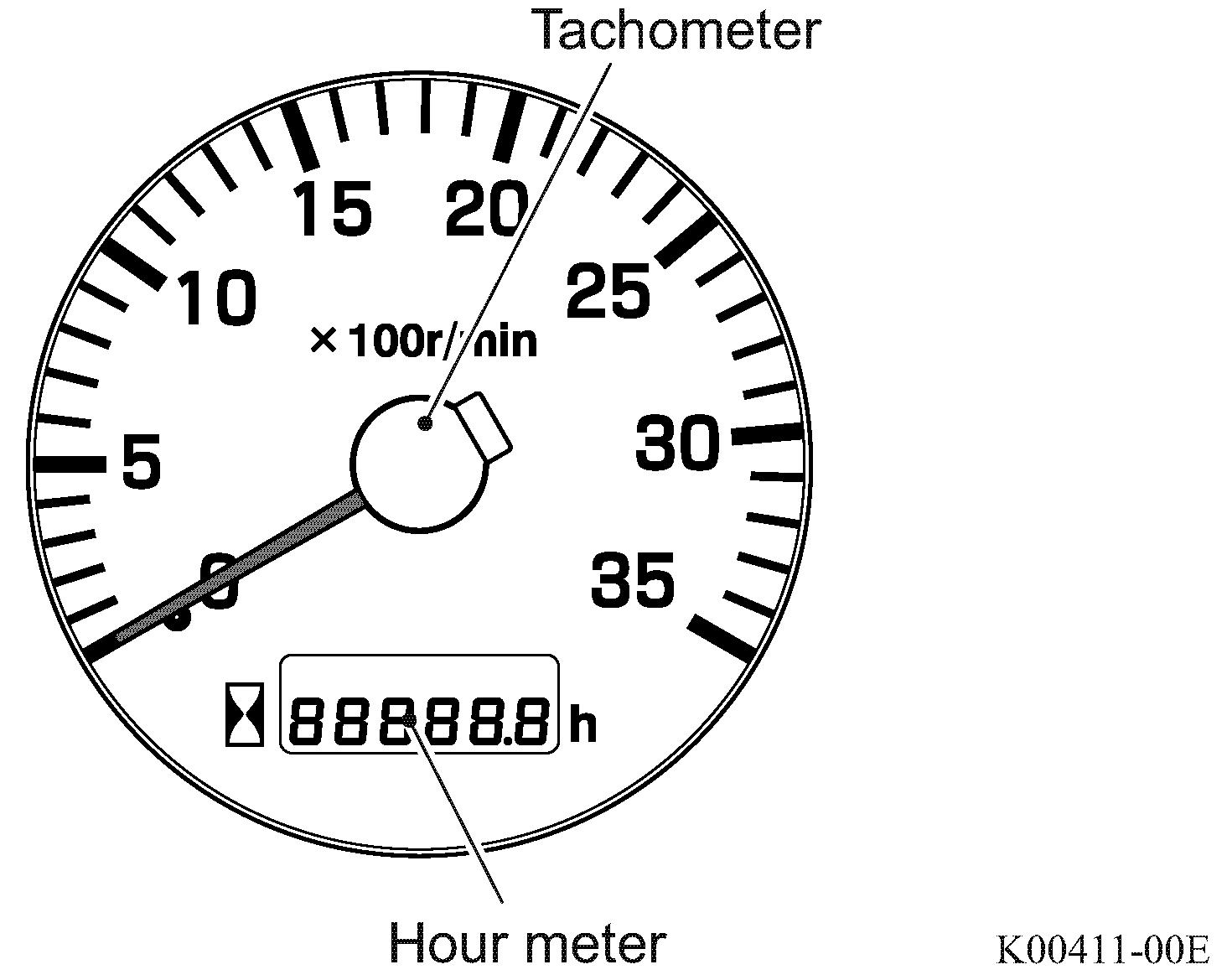
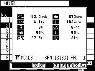
[1]: Vehicle speed [6]: Engine speed [2]: Odometer
[11]: Vehicle error code (e.g.; M0103: Indication of the internal error of the meter ECU)
[12]: Vehicle error SPN (Suspect Parameter Number: data classification number) CAN communication error For the error code list, see the service manual for DCU2 & VCU (W303-****).
[13]: Vehicle error FMI (Failure Mode Indicator: Error mode indication) CAN communication error <SAE J1939> (Cummins engine: data displayed, Mitsubishi engine: no data)
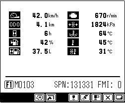
The error code displayed here is reference information.
For detail, check the hour meter display
3.4 Vehicle error Information
When the vehicle error information is obtained from the CAN port, the vehicle error information is displayed cyclically in the bottom section of sub screen shown in Fig. 3.4.1. At this time, pressing the < > key displays the error code table of Fig. 3.4.2.
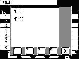
Reference: Error information table
C - 4 Error Code
4.1 Classification of error code
The error code is displayed with the numerical value having four digits. The first digit (E1) indicates the error group. The following three- digit number indicates the individual code within the error group.
E1 E2 E3 E4
Individual code
Group code
Group 0: Warning (Refer to Chapter B 3.2 Warning Code and Model Comparison Table)
Group 1: Communication device (transmitter, etc.) error
Group 2: Detector abnormality or abnormal combination of detectors
Group 3: AML internal abnormality (system abnormality). When this abnormality occurs, the execution of control software is aborted.
For about the error code table, refer to “4.4 Error Code Table.”
4.2 Error history
The error codes from group 1 to 3 are stored in the AML together with the error occurrence time. (Note 1) The maximum of 50 error items are stored in the chronological order of occurrence. When the number of error items exceeds 50, the oldest record is deleted each time a new error occurs.
Note 1: The error code in group 3 is rarely stored.
4.3 Error notification
When the AML detects an error, it displays the error code on the LCD and, at the same time, it outputs the beep sound to notify that an error has occurred. The error code continues to be displayed while the error exists.

When two or more errors occur simultaneously, each of the error codes is displayed.
4.4 Error code table
4.4.1 Communication device error (transmitter, etc.)
- Crane operation
: All the operations are possible.
: All the operations are stopped.
Port 1: Serial port connected with signal transmitter (for jib)
Port 2: Serial port connected with MDT (Multiplex Data Transmitter)
Serial port transmission line 1 open
Notification is issued that the transmitter connected with port 1 cannot receive data from the AML. (Transmission break)
E1001
Cause: Communication line from AML to transmitter is open Radio wave interference, device malfunction
Remedy: Check the wiring to the transmitter for conductivity. If no conductivity exists, replace or repair the wiring. Replace the transmitter or AML’s power circuit board.
Serial port transmission line 2 open
Notification is issued that the transmitter connected with port 2 cannot receive data from the AML. (Transmission break)
E1002
Cause: Communication line from AML to transmitter is open Radio wave interference, device malfunction
Remedy: Check the wiring to the transmitter for conductivity. If no conductivity exists, replace or repair the wiring. Replace the transmitter or AML’s power circuit board.
Serial port reception line 1 open
The AML cannot receive data from the transmitter connected with port 1. (Reception break)
E1003
Cause: Communication line from transmitter to AML is open Radio wave interference, device malfunction
Remedy: Check the wiring to the transmitter for conductivity. If no conductivity exists, replace or repair the wiring. Replace the transmitter or AML’s power circuit board. Replace the serial port fuse of AML.
Serial port reception line 2 open
The AML cannot receive data from the transmitter connected with port 2. (Reception break)
E1004
Cause: Communication line from transmitter to AML is open Radio wave interference, device malfunction
Remedy: Check the wiring to the transmitter for conductivity. If no conductivity exists, replace or repair the wiring. Replace the transmitter or AML’s power circuit board. Replace the serial port fuse of AML.
Transmitter 1 defect Transmitter connected with port 1 has detected an internal abnormality.
E1005
Cause: Transmitter malfunction Refer to transm itter repair manual.
Remedy: Replace the defective transmitter.
Transmitter 2 defect Transmitter connected with port 2 has detected an internal abnormality.
E1006
Cause: Transmitter malfunction Refer to transmitter repair manual.
Remedy: Replace the defective transmitter.
E1007
Transmitting data error at serial port 1
Transmitter connected with port 1 issued a notification that an abnormality is present in the data received from the AML.
Cause: Communication line from AML to transmitter is open. Radio wave interference, device malfunction
Remedy: Turn off any device which is emitting strong noise. Check the signal wire for poor connection. Repair or replace the wiring as appropriate.
Transmitting data error at serial port 2
Transmitter connected with port 2 issued a notification that an abnormality is present in the data received from the AML.
E1008
Cause: Communication line from AML to transmitter is open Radio wave interference, device malfunction
Remedy: Turn off any device which is emitting strong noise. Check the signal wire for poor connection. Repair or replace the wiring as appropriate.
Receiving data error at serial port 1
The AML cannot receive the data correctly from the transmitter connected with port 1.
E1009
Cause: Communication line from AML to transmitter is open Radio wave interference, device malfunction
Remedy: Turn off any device which is emitting strong noise. Check the signal wire for poor connection. Repair or replace the wiring as appropriate.
Receiving data error at serial port 2
The AML cannot receive the data correctly from the transmitter connected with port 2.
E1010
Cause: Communication line from AML to transmitter is open Radio wave interference, device malfunction
Remedy: Turn off any device which is emitting strong noise. Check the signal wire for poor connection. Repair or replace the wiring as appropriate.
Transmitter type improper (serial port 1)
The type of transmitter connected with port 1 is incorrect.
E1011
Cause: Transmitter malfunction, incorrect connection
Remedy: Connect a proper transmitter to the serial port.
Transmitter type improper (serial port 2)
The type of transmitter connected with port 2 is incorrect.
E1012
Cause: Transmitter malfunction, incorrect connection
Remedy: Connect a proper transmitter to the serial port.
CAN port 1 reception trouble
The data on the bus connected with the CAN port 1 cannot be acquired correctly. (Reception abnormality)
E1101
Cause: Bus connected with CAN1 is open or short. Device malfunction
Remedy: Perform inspection for the above possible cause.
CAN port 2 reception trouble The data on the bus connected with the CAN port 2 cannot be acquired correctly. (Reception abnormality)
E1102
Cause: Bus connected with CAN2 is open or short. Device malfunction
Remedy: Perform inspection for the above possible cause.
Interrupted communication from ICF to AML
E1104
The data from the ICF connected with the CAN port cannot be acquired correctly. (Reception abnormality)
Cause: Bus connected with CAN is open or short. Device malfunction.
E1105
Interrupted communication from DCU to AML
The data from the DCU connected with the CAN port cannot be acquired correctly. (Reception abnormality)
Cause: Bus connected with CAN is open or short. Device malfunction.
E1106
Interrupted communication from TMC CCS to AML
The data from the TMC CCS connected with the CAN port cannot be acquired correctly. (Reception abnormality)
Cause: Bus connected with CAN is open or short. Device malfunction.
Interrupted communication from VCU to AML
E1107
The data from the VCU connected with the CAN port cannot be acquired correctly. (Reception abnormality)
Cause: Bus connected with CAN is open or short. Device malfunction.
Interrupted communication from ESP Ctrl to AML
E1108
The data from the ESP controller connected with the CAN port cannot be acquired correctly. (Reception abnormality)
Cause: Bus connected with CAN is open or short. Device malfunction.
E1109
Interrupted communication from AML to ESP Ctrl
The data from the AML-C connected with the CAN port cannot be acquired correctly. (Reception abnormality)
Cause: Bus connected with CAN is open or short. Device malfunction.
E1110
Interrupted communication from Engine ECU to AML
The data from the engine ECU connected with the CAN port cannot be acquired correctly. (Reception abnormality)
Cause: Bus connected with CAN is open or short. Device malfunction.
E1111
Interrupted communication from Retarder ECU to AML
The data from the retarder ECU connected with the CAN port cannot be acquired correctly. (Reception abnormality)
Cause: Bus connected with CAN is open or short. Device malfunction.
E1112
Interrupted communication from combination meter to AML
The data from the CMA connected with the CAN port cannot be acquired correctly. (Reception abnormality)
Cause: Bus connected with CAN is open or short. Device malfunction.
4.4.2 Detector abnormality or abnormal combination of detectors
Error code Error message
Boom length detector trouble
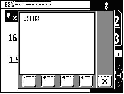
E2003
E2004
E2005
E2006
E2007
E2009
E2010
Description
The detection value of boom length detector is out of the normal range.
Normal range: 5 to 95% (0.25 to 4.75 V)
Cause: Detector malfunction, signal line open/short circuit, board malfunction
Remedy: Perform inspection for the above possible cause. The status of any input from the detector can be checked using the “Ai check” function from the “Maintenance” menu.
Boom angle detector trouble
The detection value of boom angle detector is out of the normal range.
Normal range: 5 to 95% (0.25 to 4.75 V)
Cause: Detector malfunction, signal line open/short circuit, board malfunction
Remedy: Perform inspection for the above possible cause. The status of any input from the detector can be checked using the “Ai check” function from the “Maintenance” menu.
Jib length detector trouble
The detection value of jib length detector is out of the normal range.
Normal range: 5 to 95% (0.25 to 4.75 V)
Cause: Detector malfunction, signal line open/short circuit, board malfunction
Remedy: Perform inspection for the above possible cause. The status of any input from the detector can be checked using the “Ai check” function from the “Maintenance” menu.
Jib angle detector trouble
The detection value of jib angle detector is out of the normal range.
Normal range: 5 to 95% (0.25 to 4.75 V)
Cause: Detector malfunction, signal line open/short circuit, board malfunction
Remedy: Perform inspection for the above possible cause. The status of any input from the detector can be checked using the “Ai check” function from the “Maintenance” menu.
Jib angle detector trouble
The detection value of the jib angle detector (detection of angle to ground) is out of the normal range.
Normal range: 5 to 95% (0.25 to 4.75 V)
Cause: Detector malfunction, signal line open/short circuit, board malfunction
Right front outrigger length detector trouble
The detection value of front right outrigger length detector is out of the normal range.
Normal range: 5 to 95% (0.25 to 4.75 V)
Cause: Detector malfunction, signal line open/short circuit, board malfunction
Remedy: Perform inspection for the above possible cause. The status of any input from the detector can be checked using the “Ai check” function from the “Maintenance” menu.
Right rear outrigger length detector trouble
The detection value of rear right outrigger length detector is out of the normal range.
Normal range: 5 to 95% (0.25 to 4.75 V)
Cause: Detector malfunction, signal line open/short circuit, board malfunction
Remedy: Perform inspection for the above possible cause. The status of any input from the detector can be checked using the “Ai check” function from the “Maintenance” menu.
Error code Error message Description
Left front outrigger length detector trouble
The detection value of front left outrigger length detector is out of the normal range.
Normal range: 5 to 95% (0.25 to 4.75 V)
E2011
Cause: Detector malfunction, signal line open/short circuit, board malfunction
Remedy: Perform inspection for the above possible cause. The status of any input from the detector can be checked using the “Ai check” function from the “Maintenance” menu.
Left rear outrigger length detector trouble
The detection value of rear left outrigger length detector is out of the norm al range.
Normal range: 5 to 95% (0.25 to 4.75 V)
E2012
Cause: Detector malfunction, signal line open/short circuit, board malfunction
Remedy: Perform inspection for the above possible cause. The status of any input from the detector can be checked using the “Ai check” function from the “Maintenance” menu.
Slewing angle detector 1 trouble
Although the slewing dead angle detection is OFF, the slewing angle detector 1 output is in the ON range of slewing dead angle detection.
Abnormality is detected only when the slewing dead angle detection is available.
E2017
Normal range: Set with by-models data
Cause: Detector malfunction, signal line open/short circuit, board malfunction
Remedy: Perform inspection for the above possible cause. The status of any input from the detector can be checked using the “Ai & Di check” function from the “Maintenance” menu.
E2019
Slewing angle detector 2 trouble
Although the slewing dead angle detection is ON, the slewing angle detector 2 output is in the OFF range of slewing dead angle detection.
Abnormality is detected only when the slewing dead angle detection is available.
Normal range: Set with by-models data
Cause: Detector malfunction, signal line open/short circuit, board malfunction
Remedy: Perform inspection for the above possible cause. The status of any input from the detector can be checked using the “Ai & Di check” function from the “Maintenance” menu.
Slewing angle detector 1 and 2 are mounted with 180° positional difference, and the difference has deviated from the normal range. Normal range: Voltage output difference between detectors is 48.6 to 54.3%. (Set with by-models data)
Cause: Detector malfunction, signal line open/short circuit, board malfunction
Remedy: Perform inspection for the above possible cause. The status of any input from the detector can be checked using the “Ai check” function from the “Maintenance” menu.
The detection value of the telescoping cylinder length detector is out of the normal range.
Normal range: 0.25 to 4.75 V
Cause: Detector malfunction, signal line open/short circuit, board malfunction
E2023
Moment trouble
Load calculation value is negative. When the civil engineering input Di is "During civil engineering work," the abnormality will not be judged.
Cause: Detector malfunction, signal line open circuit, board malfunction
Remedy: Perform inspection for the above possible cause.
Elevating rod pressure trouble
The detection value of elevating cylinder's rod side pressure detector is out of the normal range, and the status continues for 5 seconds in low pressure side or for 1 second in high pressure side.
E2030
Normal range: 4 to 95% (0.20 to 4.75 V)
Cause: Detector malfunction, signal line open circuit, board malfunction
Remedy: Perform inspection for the above possible cause.
Elevating cylinder pressure trouble
The detection value of elevating cylinder's cylinder side pressure detector is out of the normal range.
Normal range: 5 to 95% (0.25 to 4.75 V)
E2031
Cause: Detector malfunction, signal line open circuit, board malfunction
Remedy: Perform inspection for the above possible cause.
Lever 1 neutral trouble
E2048
The input voltage of lever 1 is not consistent with the status of the neutral detection switch. (when the switch is at the neutral position) Or, lever 1 is not at the neutral position when the power is turned on, when the emergency operation is canceled, or when the lever stand recovers from the stowed state.
Cause: Joystick (JS) malfunction, wiring open/short circuit, board malfunction
*1: Only the series in which abnormality has been detected is stopped. (Other series can be operated.)
E2084
Telescoping operation trouble
The detection value of the boom length detector changes despite the fact that no output is provided to the proportional solenoid valve for telescoping control. (changes toward the extension side)
Cause: Contamination of hydraulic pressure system, solenoid short circuit, detector malfunction, board malfunction
*3: Venting is possible. Only the operation toward the opposite direction of the series in which abnormality has been detected is possible. Other series can be operated.
Boom section detection switch trouble
E2087
Multiple boom section detection switches are turned on simultaneously.
Cause: Wiring open/short circuit, detector malfunction, board malfunction
Boom section detection switch trouble
The telescoping cylinder length is not consistent with the status of the boom section detection switch.
E2089
Cause: Disorderly winding/adjustment failure/malfunction of the cylinder length detector Adjustment failure/malfunction of the boom section detector wiring open/short circuit, detector malfunction, board malfunction
E2090
B-pin detector trouble
Abnormality of the fixing pin between the booms. (pin cannot be inserted or removed)
The B-pin LOCK and UNLOCK detectors are both turned on.
Cause: Adjustment failure/malfunction of the B-pin detector
Wiring open/short circuit, detector malfunction, board malfunction
C-pin detector trouble
Abnormality of the fixing pin between the boom and telescoping cylinder.
(pin cannot be inserted or removed)
E2091
The C-pin LOCK and UNLOCK detectors are both turned on.
Cause: Adjustment failure/malfunction of the C-pin detector
Wiring open/short circuit, detector malfunction, board malfunction
B-/C-pin trouble (combination abnormality)
E2092
The combination of the detected B-/C-pin status inputs is abnormal. A state in which both the B-pin and C-pin are removed is detected.
Cause: Adjustment failure or malfunction of the B-/C-pin detector Wiring open/short circuit, detector malfunction, board malfunction
Boom section detection-C-pin combination trouble
C-pin UNLOCK detection is turned off (pin is about to be extended) with the boom section detection turned off.
E2093
Cause: Adjustment failure/malfunction of the boom section detector and C-pin detector
Wiring open/short circuit, detector malfunction, board malfunction
Boom telescoping condition reset
The single-cylinder type boom has not been initialized.
E2094
Cause: Initialization before operation, board malfunction
*1: Only telescoping operation is stopped. (Other operations are possible.)
E2106
Telescoping operation trouble
The detection value of the boom length detector changes despite the fact that no output is provided to the proportional solenoid valve for telescoping control. (changes toward the retraction side)
Cause: Contamination of hydraulic pressure system, solenoid short circuit, detector malfunction, board malfunction
*3: Venting is possible. Only the operation toward the opposite direction of the series in which abnormality is detected is possible. Other series can be operated.
E2113
A2B signal trouble
Two-blocking signal is broken or short to the power source line.
Cause: Two-blocking signal line open/short circuit, board malfunction
Remedy: Perform inspection for the above possible cause.
Boom section detection-B-pin combination trouble
E2119
Anti-two-block (A2B) device works.
B-pin LOCK detection is turned off (B-pin is about to be removed) when the C-pin is not inserted.
Cause: Adjustment failure/malfunction of the boom section detector and B-pin detector Wiring open/short circuit, detector malfunction, board malfunction
E2167
2nd boom length detector trouble