2 minute read
Components of AML System


3. Backward stability stop:
When the boom is raised over the specified angle, the output from Do1 stops and the crane operation stops automatically due to AML vent. Recovery from the automatic stop is possible only by boom raising.
4. Work range limit stop:
When the boom head approaches a pre-registered limit of the work range, slow stop function works and the AML energizes the corresponding proportional solenoid valve. It slowly closes the pilot pressure circuit for the main control valve to decelerate crane operation until the main control valve becomes neutral and the output from Do1 stops to make AML vent disable crane operation. For slewing limit, however, the proportional solenoid valve makes the main control valve immediately to stop the crane. In this case the crane does not slew beyond the limit even if the AML override is activated, and it slews only toward within of the limit.
[NOTICE]
◆ Configurations may vary depending on models or specifications.
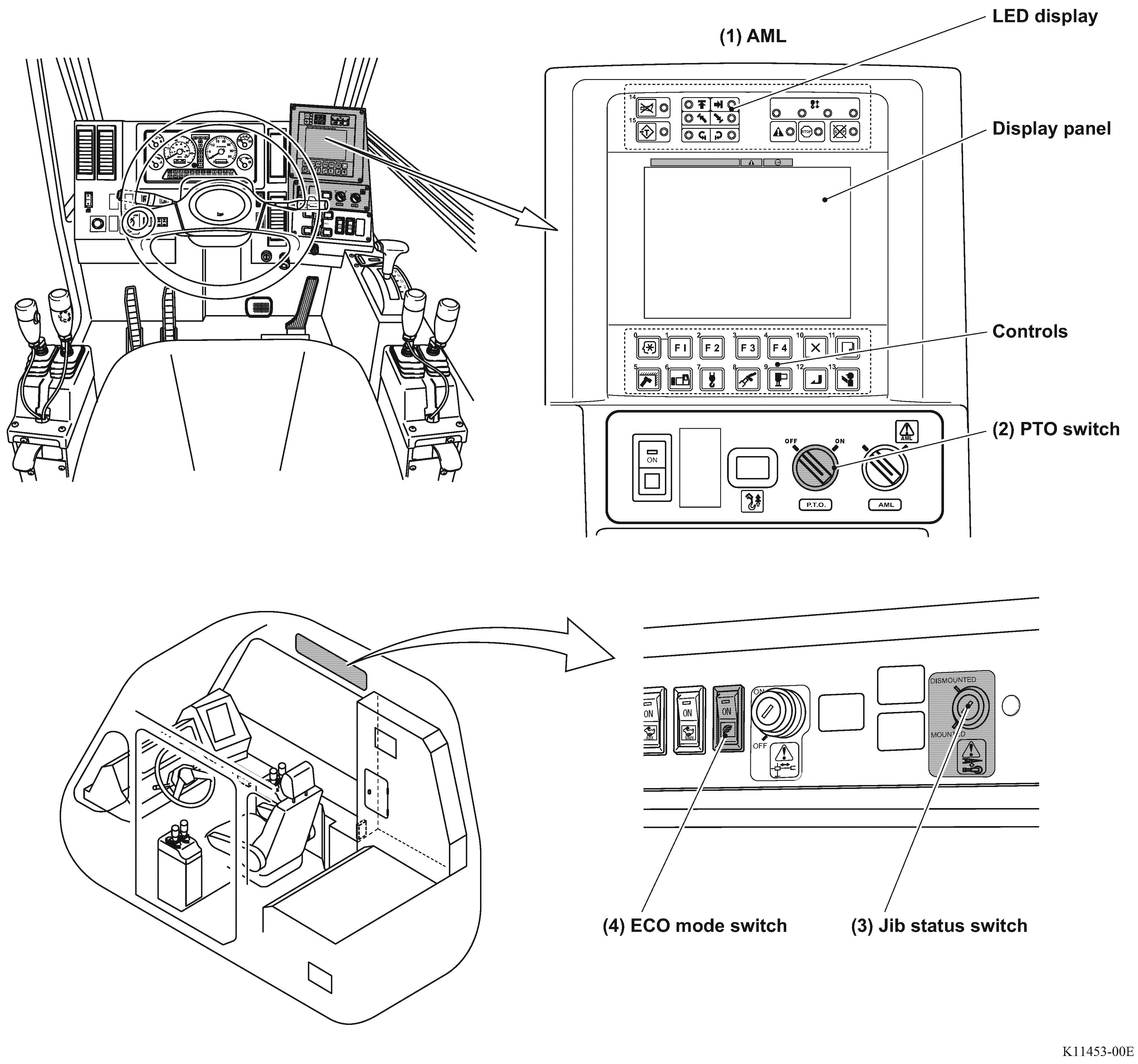
1.2 Display unit
Composition of the display unit
1. The LED display indicates the limit state of each work range, rotation state of the winch drum, and AML control state. The display panel indicates the moment ratio, crane state, outrigger state, slewing position, and error code.

When the PTO switch is set to "ON," the AML starts
1.2.1 Display panel
(ex. GR-800EX-3)
ECO mode (Low fuel consumption mode)
Notice
• The AML is not a hook load indicator. The hook load indication is a reference value, and not a correct mass of the lifted load.
(1) Moment load ratio display
Shows the moment load ratio with a bar graph.
(2) Moment load ratio index

Shows the moment load ratio by bar graph : safe (green), warning (yellow), or critical (red).
(3) Jib lift indicator symbol
Appears when the jib lift is registered. Flashes when the jib set state is registered to the AML.
(4) Single top lift indicator symbol
Appears when the single top lift is registered.
(5) Crane status indicator (A-1)
(6) Crane status indicator (A-2)
(7) Crane status indicator (A-3)
(8) Crane status indicator (A-4)
(9) Crane status indicator (B-1)
(10) Crane status indicator (B-2)
The indicator (icon) shows a crane state. Refer to "Operation Indicator Display" (Chapter B-1) for the meaning of the icons.
(11) Slewing position display
Shows the current slewing position. The display is graduated in 45°.
(12) Front position symbol
Appears when the boom is directed to the front of the vehicle.
(13) On-rubber status indicator symbol
Flashes during on-rubber creep operation, and turns on steadily during on-rubber stationary operation.
(14) Outrigger status indicator symbol
Indicates the extension width of outriggers. The outer frames of the symbol represent the maximum available steps of the outrigger extension, and the inner frames (black-filled segments) represent the current step of outrigger extension.
(15) Boom Lift Indicator Symbol
Appears when the boom lift is registered to the AML.
(16) Fuel consumption indicator
Shows the fuel consumption during crane operation.
(17) ECO mode indicator
Lights up when ECO mode switch is on and displays current mode such as ECO mode 1 or ECO mode 2.