2 minute read
Maintenance Mode


When a node is connected to the CAN, the state of each node is also displayed as shown in Fig. 2.5.2.
<Description of display contents>
Port CAN1 to CAN2 : CAN communication port
Signal Name
ICF : Node name of information controller for Telematics
VCU : Node name of controller for vehicle
DCU : Node name of controller for display
CMA : Node name of Combination meter Assy
Value for the data reception failure count (since the power is turned on). Used as a guideline of the communication state.
2.6 Do check
Displays the status of digital output. In the maintenance main menu of Fig. 1.3.1, select "Do Check," and press the < > key to display the Do check screen shown in Fig. 2.6.1. Pressing the < > key (previous page) or the < > key (next page) changes the pages. Also, when the Do item is selected (highlighted) using the < > key (scroll up) or the < > key (scroll down), all type of auto stop solenoid valve is the output status of selected output can be reversed while the < > key is pressed. To go back to the maintenance main menu, press the < > key.
Normally energized type.
<Description of display contents>
Port
Do1 to Do16 : Output from AML
Os11 to Os18: Transmitter output via serial port 1
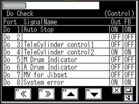
Os21 to Os28: Transmitter output via serial port 2
Out: Current output state ON: Output ON OFF: Output OFF
FB: Current output feedback state ON: Output ON OFF: Output OFF State
(Monitor): Control output monitor
(Check): Check output monitor
Output of a selected Do port “out” can be reversed while “Check key” is being pushed (To ON -> OFF and OFF -> ON). Therefore, operation of the output of all Port can be confirmed.
When solenoid valve for Auto stop operates correctly crane is operated while pushing “Check key” even when stopped automatically due to a trouble, and to store it. (While outputting the revers signal of “Do1, Auto Stop signal”.)
2.7 Ao check
Displays the status of analog output. In the maintenance main menu of Fig. 1.3.1, select "Ao Check," and press the < > key to display the Ao check screen shown in Fig. 2.7.1.
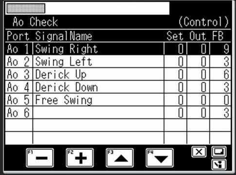
To perform the test output, select the set value of item (highlighted) using the < > key (scroll up) or the < > key (scroll down). The set value is increased or decreased using the < > key (+) or the < > key (-). While the < > key is pressed, the set test value can be output.
To go back to the maintenance main menu, press the < > key.
To perform the continuous test output, press the < > key and the < > key. In this case, the inspection output can be performed while increasing/decreasing the set value by using the < > key (+) or the < > key (-).
To quit the continuous test output, press any of the < > key, the < > key, the < > key (scroll up), or the < > key (scroll down).
<Description of display contents>
Set : Set value for test output (D/A value: Selectable from 0 to 255)
Out : Current output value (D/A value: 0 to 255)
FB : Feedback current value (D/A value: 0 to 255)
State
(Monitor) : Control output monitor
(Check) : Check output monitor
(Check) : Continuous check output monitor
Can not slewing (swing) when the output value (D/A value) of “Ao1 Port” is 200 or more. But slewing when the output value change to 0 with F4 key (scroll down).
When it becomes “Open completely = Full stroke” when the impressed current is 0, and 0.8 amperes (D/A value 255) are impressed, the Pilot pressure that controls the stroke of “Slewing control value” becomes “Close completely = Zero stroke”
Therefore, flow rate from the pump can not supply to the slewing motor, and the slewing stops.