3 minute read
Adjustment mode


D - 4 Valve Adjustment
The characteristics of actuator operation speed necessary for the slow stop to AML valve control output (D/A command value) are stored as the valve output adjustment value. Note: Slow stop function corresponding to the proportional solenoid valve does not work until the valve adjustment is completed. The subjected crane operations are described below.
Advertisement
- Slewing (right, left) operation
- Elevation (raising, lowering) operation
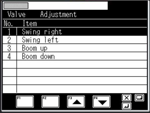
4.1 Adjustment Sub Menu
When "Valve Adjustment" is selected in the adjustment main menu of Fig. 1.3.3, the selection screen for subjected adjustment work is displayed as shown in Fig. 4.1.1 Press the < > key (backward) or the < > key (forward) to highlight the selected adjustment item. To go back to the adjustment main menu, press the < > key. The mark " " is shown at the left of the item that is already adjusted.
4.2 Slewing Output Adjustment (Offset Method)
By the adjustment of slewing output (current) Ao1, Ao2, (CN6-pin1, pin3), the stop point is adjusted. The current value to the proportional solenoid valve that controls the pilot pressure given to the slewing control valve’s spool is increased by the F2 key. The speed of the slewing table decreases as the amount of oil supplied from the slewing control valve to slewing motor is gradually decreases (opening / clearance between the slewing control valve body and spool decreases). Finally, hydraulic oil is not supplied to the slewing motor any more (the clearance between the valve body and spool becomes none), and the slewing table stops. The deceleration condition varies depending on the crane serial No. Adjustm ent is necessary depending on every serial No.
In the valve adjustment item selection screen shown in Fig. 4.1.1, select "Swing (slewing) right" or "Swing (slewing) left," and then press the < > key to display the slewing output adjustment display shown in Fig. 4.2.1.
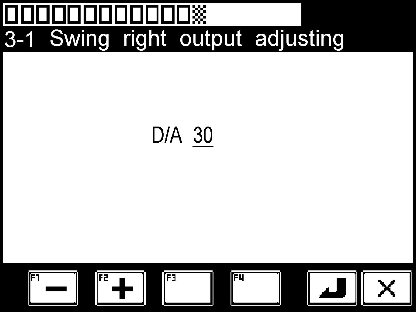
the adjustment according to the procedure below.
- In the specified condition (boom fully retracted, jib stowed), set the engine speed to the maximum, and change a full lever stroke to the subjected slewing direction. (Confirm the level with O/R max. extended)
- In the slewing operation status, while increasing the D/A value by pressing the < > key (+), search the position where the value stops.
- Once the position where D/A value stops, press the < > key to store the data. The screen automatically returns to the valve adjustment menu shown in Fig. 4.1.1.
- To go back to the valve adjustment menu of Fig. 4.1.1 without storing the adjustment value, press the < > key.
4.3 Slewing Output Adjustment (Characteristics Measurement Method)
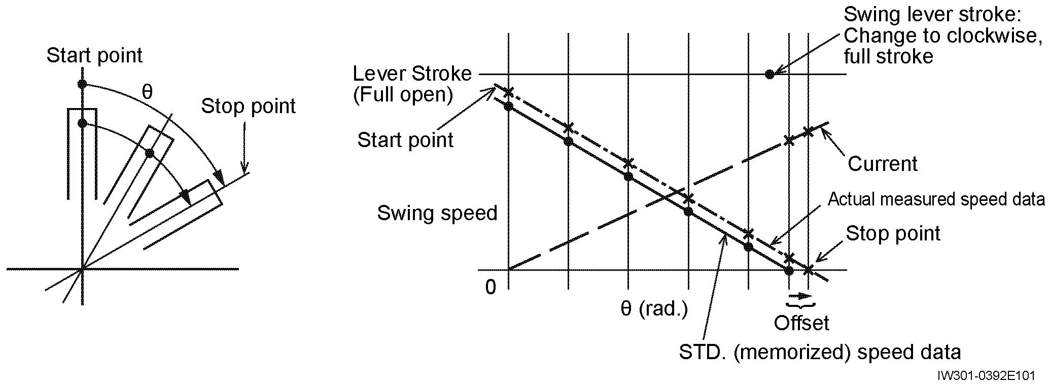
The offset method keeps only the stop points in memory, so it may fail to decelerate the crane smoothly in some direction clockwise and counterclockwise. To achieve smooth deceleration, characteristics measurement method is used for adjustment of the outputs. With the crane set in the specified configuration for measurement (the crane is set level on extended outriggers; the engine speed is maximum; the slewing lever is shifted to the full stroke), the degree of change of the slewing speed according to the current output to the proportional solenoid valves is measured. Not only stop points of the slewing table but the starting point of deceleration and the data during deceleration are measured and kept in memory. The characteristics measurement method smoothly decelerates and stops boom slewing on the basis of these measured characteristics.
In the valve adj. item selection screen shown in Fig. 4.1.1, select "Swing (slewing) right" or "Swing (slewing) left," then press the < > key to display the slewing output adjustment display of Fig. 4.3.1.

4.3.1 Adjustment Procedure
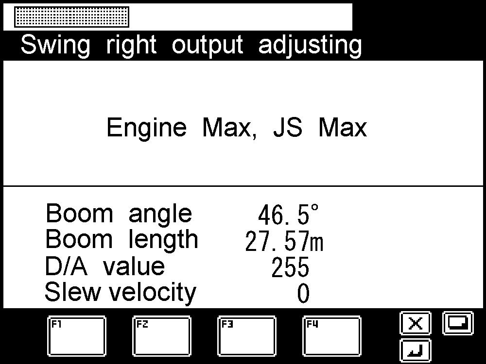
With the screen of Fig. 4.3.1 displayed, press the < > key to change the display to the screen shown in Fig. 4.3.2.
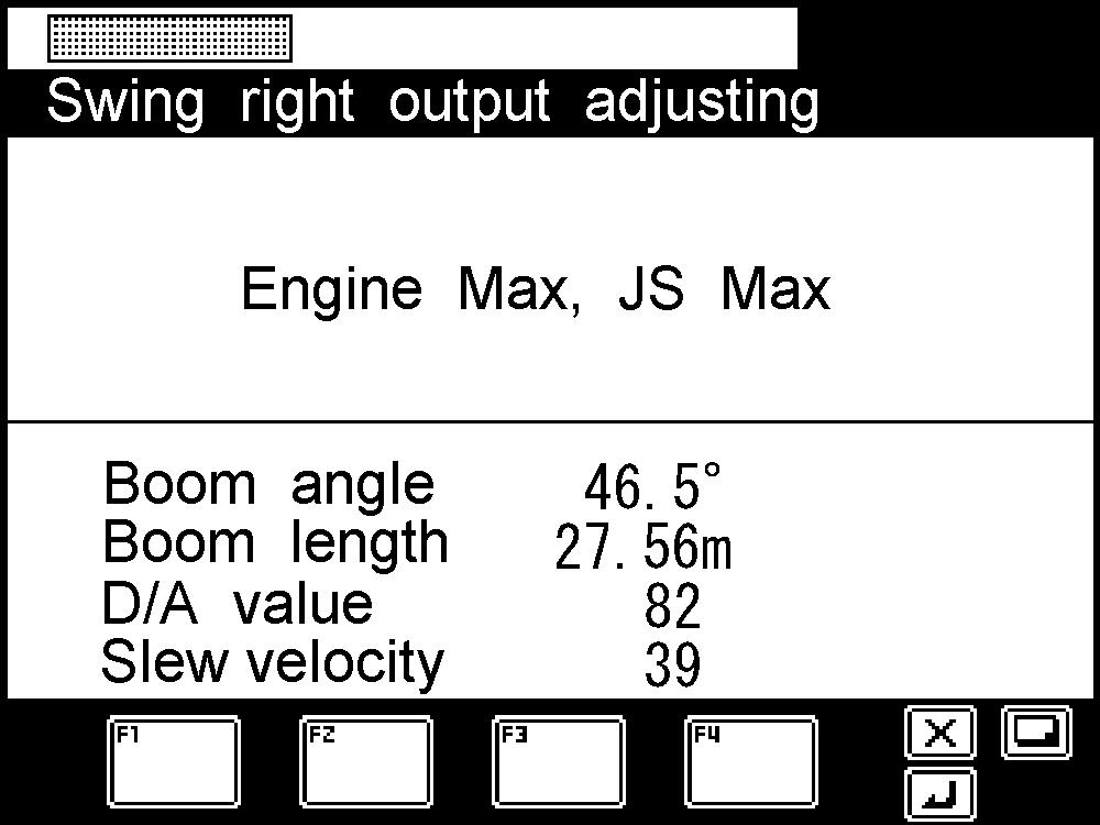
- After setting the posture to the specified one, set the engine speed to the maximum, and then perform a full lever operation to start the measurement. [Attention]
Remember that the measurement will be started as soon as the lever is operated, even if the crane condition differs from the specified crane condition.
When the measurement is started unexpectedly, leave the lever at the neutral position to terminate the measurement. Subsequently, start the process again from the status indicated in Fig. 4.3.1.
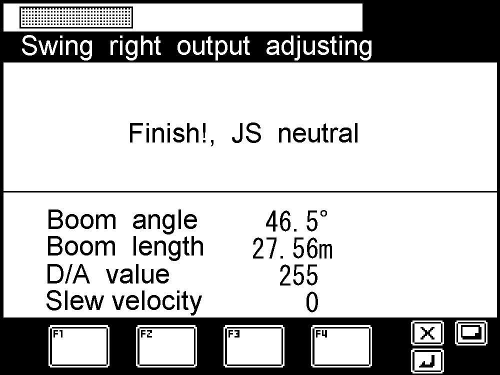
When the measurement is started, the slewing speed is gradually increased. After the maximum slewing speed is reached, the speed is decelerated with specified time intervals. When "Slew velocity" in the screen of Fig. 4.3.3 becomes zero, the measurem ent is completed. Then, the screen changes to the one shown in Fig. 4.3.4.
With the screen of Fig. 4.3.4 displayed, setting the lever to the neutral position automatically changes the screen to Fig. 4.3.1, and the slewing output adjustment is completed.