3 minute read
Adjustment mode


<Operation method>
The currrent setup stae is enclosed by a frame. Press the < > key (scroll up) or the < > key (scroll down) key to select the state to set up, and press the < > key to register the selected state and go back to the screen of Fig. 6.1.1. Perss the < > key , to go back to the set up performance menu of Fig. 6.1.1 without registartion.
Advertisement
6.1.1 Details of menu items
[1] When specification selection flag of winch drum position adjustment value selection is " rear←→ front / rear" (0)
(A) When the specification selection flag of winch drum selection availability is "1" (available) and selection is performed by pop-up menu for winch drum position selection from the user prset menu (B-4.5)
Change of the winch drum position selection adjustment value is possible only by the setting of the user preset menu. (See B-4.5.6)
(1) “Winch drum front / rear”
The winch drum position is determined only by the boom / jib lift state, and the winch position cannot be selected in the user preset menu.
The position for boom lift state is fixed in the front position
The position for S/T and jib lift states is fixed in the rear position.
(2) “W inch drum rear”
The winch drum position is determined by the boom / jib lift state, and the selected content of the winch position select in the user preset menu.
The position for boom lift state is fixed in the rear position
The position for S/T and jib lift states is fixed in the position selected in the user preset menu.
[2] When specification selection flag of winch drum position adjustment value selection is " front←→front / rear" (1)
(A) When the specification selection flag of winch drum selection availability is "1" (available) and selection is performed by pop-up menu for winch drum position selection from the user prset menu (B-4.5) Change of the winch drum position selection adjustment value is possible only by the setting of the user preset menu. (See B-4.5.6)
(1) “Winch drum front / rear”
The winch drum position is determined only by the boom / jib lift state, and the winch position cannot be selected in the user preset menu.
The position for boom lift state is fixed in the front position.
The position for S/T and jib lift states is fixed in the rear position.
(2) “W inch drum front”
The winch drum position is determined by the boom / jib lift state, and the selected content of the winch position select in the user preset menu.
The position for boom lift state is fixed in the front position.
The position for S/T and jib lift states is fixed in the position selected in the user preset menu.
D - 7 Emergency Histo ry Erase
7.1 Operation Procedure
This section describes the method to erase the registration contents of AML emergency / override switch history information (information on the date and time when the AML emergency / override switch is turned ON/OFF).
In the adjustment main menu of Fig. 1.3.3, select "Emergency History Erase" to display the AML emergency / override switch history erase screen as shown in Fig. 7.1.1.
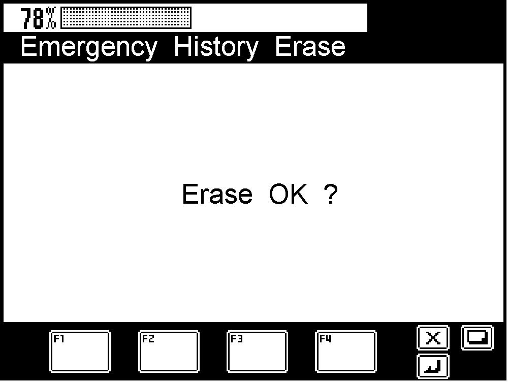
Pressing the < > key erases the AML emergency switch history. Then, the erase confirmation display appears as shown in Fig. 7.1.2.
To go back to the adjustment main menu of Fig. 1.3.3 without erasing the AML emergency / override switch history, press the < > key while the screen shown in Fig. 7.1.1 is being displayed.
7.2 Operating Conditions
This function will not be available after the operation history is erased for three times. Also, the corresponding item is not shown in the adjustment main menu of Fig. 1.3.3.
D - 8 Operation History Erase
This section describes the method to erase the registration contents of operation history information {stored data of when the crane operation is performed while the moment load ratio is exceeding the set limit value}
[NOTICE]
Before delivery to users, always repeat erasing the operation as described here three times.
8.1 Operation Procedure
In the adjustment main menu of Fig. 1.3.3, select "History Erase" to display the operation history eras e screen as shown in Fig. 8.1.1.
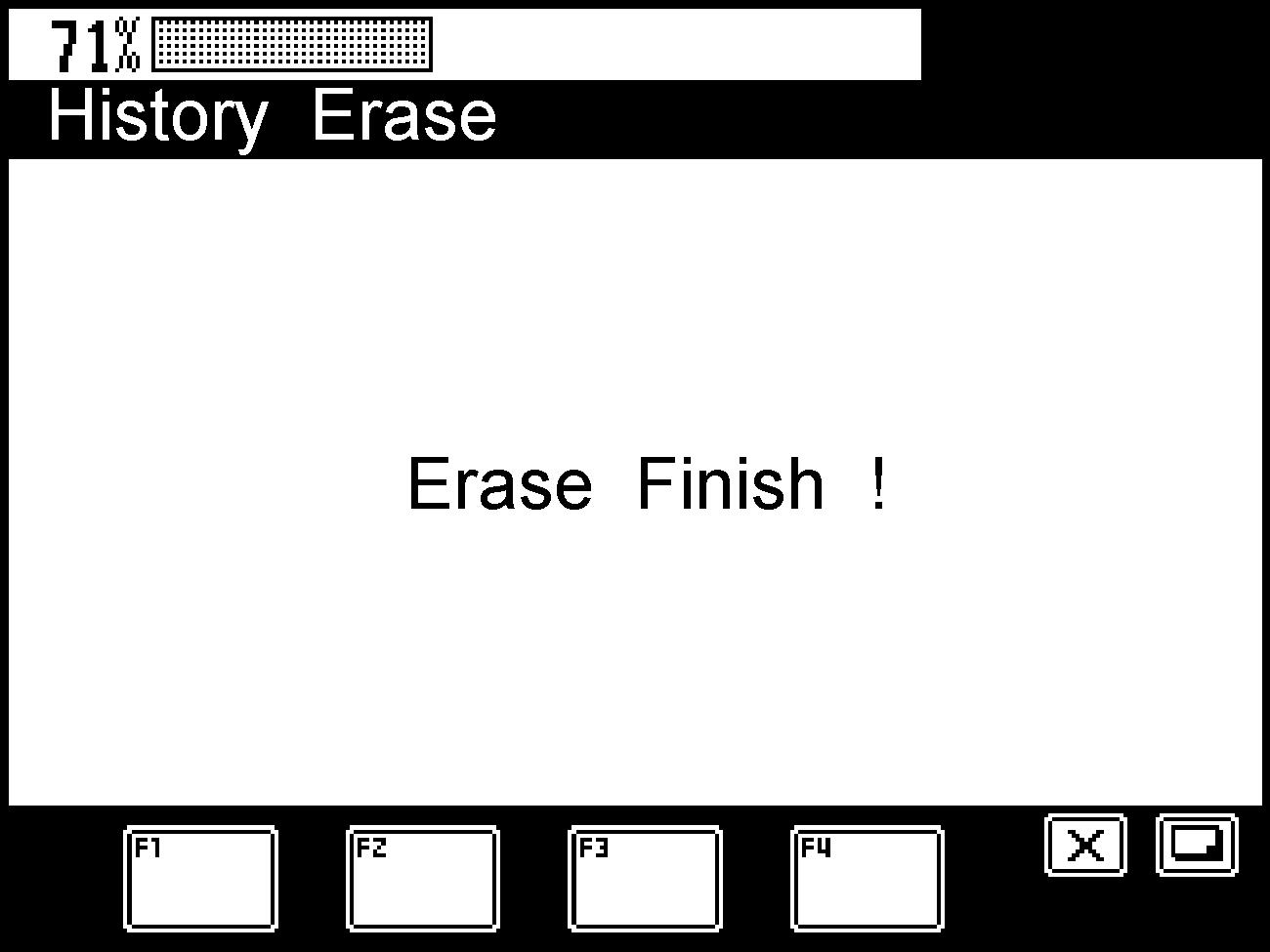

Under the status shown in Fig. 8.1.1, pressing the < > key erases the operation history. Then, the erase confirmation display appears as shown in Fig. 8.1.2.
To go back to the adjustment main menu of Fig. 1.3.3 without erasing the operation history, press the < > key while the screen shown in Fig. 8.1.1 is being displayed.
D - 9 Outrigger Emergency Setting History Erase
9.1 Operation Procedure
This section describes how to erase the registration contents of outrigger emergency setting history information. In the adjustment main menu of Fig. 1.3.3, select "O/R Emergency History Erase" to display the outrigger history erase screen as shown in Fig. 9.1.1. Pressing the < > key erases all the outrigger emergency setting history information. Then, the erase confirmation message appears as shown in Fig. 9.1.1.


To go back to the adjustment main menu of Fig. 1.3.3 without erasing the outrigger emergency setting history, press the < > key while the screen shown in Fig. 9.1.1 is being displayed.
To go back to the adjustment main menu screen of Fig. 1.3.3, press the < > key while in the screen status of Fig. 9.1.2.
9.2 Operating Conditions
This function is not available after the operation history is erased for three times, or with models t o which the outrigger emergency setting switch is not provided. Also, the corresponding item is not shown in the adjustment main menu of Fig. 1.3.3.