Maintenance Mode
Cha pte r C
Cha pte r C
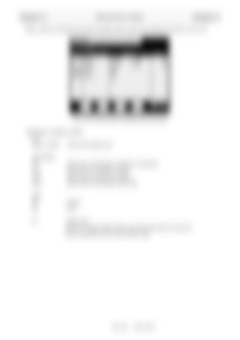
When a node is connected to the CAN, the state of each node is also displayed as shown in Fig. 2.5.2.
Fig. 2.5.2 Si check screen including CAN node state <Description of display contents> Port CAN1 to CAN2
: CAN communication port
Signal Name ICF
: Node name of information controller for Telematics
VCU
: Node name of controller for vehicle
DCU
: Node name of controller for display
CMA
: Node name of Combination meter Assy
State OK
: Normal
NG
: Error
N.L
: Noise Level Value for the data reception failure count (since the power is turned on). Used as a guideline of the communication state.
C - 11
W301-0471E


