Model 5200 High-Level Orderpicker
Section 7. Component Procedures
Drive and Brake
Drive Unit
71826_107.tif
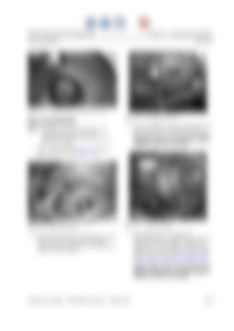
Figure 7-88.
Applying Locking Compound to Screw
7dial.tif
Figure 7-90.
Measuring Backlash NOTE: Backlash tolerance is critical to the performance of the drive unit. Incorrectly adjusted units experience premature failure.
Dial Indicator Position
3. Zero the indicator. Clasp the bottom of the gear and rotate it. Read the backlash measurement on the dial indicator. Total backlash tolerance is between 0.004 to 0.006 in. (0.10 to 0.15 mm).
1. Place a gear-locking tool on the helical gear and secure. See Figure 7-89.
7backlsh.tif 7gearfixt.tif
Figure 7-89.
Gear Locking Tool
2. Install the probe of the dial indicator at the heel of the bevel gear tooth. The dial indicator probe should be perpendicular to the gear tooth surface.
Figure 7-91.
Measure Backlash
4. If the tolerance is not within the acceptable limits, calculate any necessary adjustments to the shims. Remove the clamp nut, axle assembly, and bevel gear. Install the correct amount of shims, and repeat steps 3 and 4 of “Housing Bearing Cup and Shim Assembly” on page 7-40 . Repeat steps 1 thru 3 of this procedure until the backlash is between 0.004 to 0.006 in. (0.10 to 0.15 mm).
Publication Number: 1043922B, Revised: 2 Sept 2015
7-45


