2 minute read
Model
from Raymond 5200 High-Level Orderpicker Lift Truck Maintenance Manual SN 1000 and up - PDF DOWNLOAD
Lift Motor Removal
1.Turn the key switch OFF and disconnect the battery.
2.Remove the tractor covers. See “Tractor Covers” on page7-11.
NOTE: In the next steps you need a 5 gallon (19 liter) capacity container.
3.Drain the hydraulic fluid. See “Hydraulic Fluid” on page7-84.
4.Disconnect the hoses from the pump.
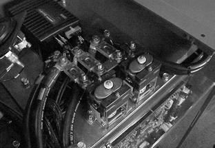
5.Use a two-wrench method to disconnect the power cables from the lift motor. See Figure7-130.
Installation
1.Add anti-seize compound (P/N990-638) to the spline shaft of the pump before mounting to the motor. See Figure7-132.
2.Mount the pump to the motor. See Figure7-131.

3.Install four bolts to secure the motor to its bracket on the tractor frame.
6.Remove the four bolts that hold the motor to the bracket. See Figure7-130.
7.Lift out the motor and pump assembly.
NOTE: Rest the motor on the bracket lip.
8.Remove the pump from the motor. See Figure7-131.
4.Connect the power cables. See Figure7-130.
5.Attach the hoses and replace the hydraulic filter. See Figure7-130.
6.Insert the drain plug in the drain hose and fill the hydraulic reservoir with new fluid. See “Lubrication Specification Chart” on pageA-2.
7.Reconnect the battery connector and turn the key switch ON. Test the lift truck operation before returning to service.
8.Install tractor and top covers.
Section 7.Component Procedures
Model 5200 High-Level Orderpicker
Horn Electrical Components
Horn
NOTE: For replacement parts information refer to the Parts Manual.
Horn Removal
1.Turn the key switch OFF and disconnect the battery connector.
2.Remove the tractor cover.
3.Disconnect the wires from the horn.
4.Remove the horn mounting bolt.
Horn Installation
1.Attach the horn to the tractor plate assembly on the front plate of the tractor and tighten the mounting bolt. See page7-6 for location. Make sure the horn bracket is isolated from the lift truck frame.
2.When replacing an old style three prong horn with a new style two prong horn, install 0.5 in. (12.7mm) heat shrink tubing (P/N611-013) over the unused spade connector.
3.Connect Horn (+) and Horn (-) wires to the new horn.
4.Fasten the unused wire back to the harness using a cable-tie or equivalent.
5.Reconnect the battery connector and turn the key switch ON.
6.Test the horn operation before returning the lift truck to service.
7.Install the tractor cover.
Publication Number: 1043922B, Revised: 2 Sept 2015
Electrical Components Fuses

Fuses Replacement
When replacing the fuses, make sure they are installed in the correct order. See Figure7-133.

NOTE: Refer also to “Fuses” on page5-14.
Publication Number: 1043922B, Revised: 2 Sept 2015
Section 7.Component Procedures
Model 5200 High-Level Orderpicker
Circuit Cards (General)
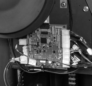
2.Remove appropriate cover(s). See “Tractor Covers” on page7-11.
3.If removing a circuit card from the tractor, remove the circuit card cover.

4.Disconnect all connectors on this circuit card.
5.Remove all screws holding the circuit card to the frame.
Installation
1.Install new circuit card with the screws you removed earlier.

2.Attach the connectors to the circuit card.
3.If installing a circuit card in the tractor, install the circuit card cover.
Use correct precautions against electrostatic discharge. See “Static Precautions” on page2-7.
NOTE: Before removing a good Carriage Manager, use the FlashWare Program to clear the memory. See “Wire Guidance” on page3-8.
Removal
1.Turn the key switch OFF and disconnect the battery.
4.Install the appropriate cover(s).
5.Reconnect the battery connector and turn the key switch ON. Test the lift truck operation before returning to service.
Publication Number: 1043922B, Revised: 2 Sept 2015
Circuit Cards (General) Electrical Components 7-70


