2 minute read
Model 5200 High-Level Orderpicker
from Raymond 5200 High-Level Orderpicker Lift Truck Maintenance Manual SN 1000 and up - PDF DOWNLOAD
Section 7.Component Procedures
Drive and Brake Drive Unit

Measuring Backlash
NOTE: Backlash tolerance is critical to the performance of the drive unit. Incorrectly adjusted units experience premature failure.
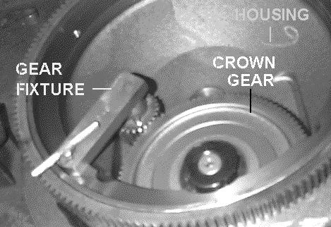
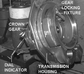
1.Place a gear-locking tool on the helical gear and secure. See Figure7-89
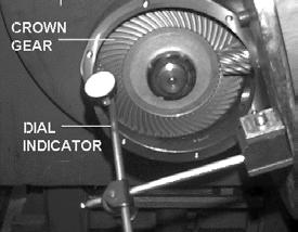
3.Zero the indicator. Clasp the bottom of the gear and rotate it. Read the backlash measurement on the dial indicator. Total backlash tolerance is between 0.004 to 0.006 in. (0.10 to 0.15 mm).

4.If the tolerance is not within the acceptable limits, calculate any necessary adjustments to the shims. Remove the clamp nut, axle assembly, and bevel gear. Install the correct amount of shims, and repeat steps 3 and 4 of “Housing Bearing Cup and Shim Assembly” on page7-40 Repeat steps 1 thru 3 of this procedure until the backlash is between 0.004 to 0.006 in. (0.10 to 0.15 mm).
Publication Number: 1043922B, Revised: 2 Sept 2015
Section 7.Component Procedures
Model 5200 High-Level Orderpicker Drive Unit Drive and Brake
5.When backlash is within the acceptable range, install the pivot ring.
Pivot Ring Assembly
1.Place a light coating of thread-locking compound (P/N 990-544) in the hole on the pivot ring assembly.
2.Line up the grease fitting hole with the grease fitting port. See Figure7-92 .
5.On the inside of the pivot ring, make sure the roll pins are installed and in good condition on either side of the bearing filler plug hole. If they are missing or damaged, install new roll pins. See Figure7-95.
3.Install the spherical bearing using a mallet or press. See Figure7-93
6.Install the radial rings so that the gap aligns with the bearing hole. Install the flat radial ring on the inside flat surface of the pivot ring. Then install the chamfered radial rings to the pivot ring. The chamfered edges must face the steel balls. The ends of the radial ring are against the roll pins. See Figure7-96 .
4.Install the grease fitting in the pivot ring assembly using a grease fitting driver and a mallet or press. See Figure7-94
Publication Number: 1043922B, Revised: 2 Sept 2015
Section 7.Component Procedures
Model 5200 High-Level Orderpicker
Drive Unit Drive and Brake
Drive Unit Assembly
1.Install the radial rings on the housing. Stagger the ends of the rings around the housing so the gaps are offset at 3, 6, and 9 o’clock. The beveled edges face the steel balls. See Figure7-98 .
2.Install the pivot ring assembly to the housing. The spherical bearing must face the spur gear. See Figure7-99
5.Install the filler plug bolts and flat washers on each side of the grease fitting. Tighten to 17 ft. lbs. (23 Nm). See Figure7-102.
3.Place one steel ball at a time into the pivot ring filler hole. Use a screwdriver to direct the steel balls first to one side then the other. See Figure7-100.
NOTE: Count the steel balls as they are inserted in the pivot ring assembly for correct pivot ring operation. The drive unit requires 67 balls. Too many balls cause binding and too few balls cause excessive motion.
Publication Number: 1043922B, Revised: 2 Sept 2015


