2 minute read
Model 5200 High-Level Orderpicker
from Raymond 5200 High-Level Orderpicker Lift Truck Maintenance Manual SN 1000 and up - PDF DOWNLOAD
Hydraulic Components
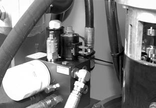
Lift Pressure Relief Valve Adjustment
1.Install a calibrated pressure gauge [3000 psi (20,682 kPa) at mid-range] in the lift pressure test port (G1). See Figure7-165.
Section 7.Component Procedures
Lift Pressure Relief Valve Adjustment b.To increase pressure, turn the adjusting screw clockwise. To decrease pressure, turn the adjusting screw counterclockwise. c.Tighten the lock nut on the lift pressure relief valve.
9.Check the pressure again. If the value has changed, repeat this procedure until the correct pressure reading is obtained.
10.Turn the key switch OFF and disconnect the battery.
11.Disconnect the pressure gauge and reinstall the cap on the lift pressure test port (G1).

2.Loosen the lock nut on the lift pressure relief valve (REL-1) and back out the high-pressure relief.
3.Make sure the emergency lower valve is closed.
4.Place a maximum rated load + 200 lb. (90.7 kg.) on the forks.
5.Start the lift system and turn the pressure relief screw clockwise until the platform starts to lift. Note the pressure required when the platform starts to elevate. On three-stage lift trucks, continue lifting until the third stage of the mast starts lifting. Record the pressure reading.
6.Lower the operator platform and remove the load.
7.Chain the mast sections together and lift or lift the operator platform until the upper limit is reached.
8.To adjust the pressure: a.Continue trying to elevate, and turn the lift pressure adjusting screw (at REL-1) to obtain a pressure reading of 100 to 300 psi (689 to 2068 kPa) greater than that required to lift maximum rated load (value recorded is step 5).
Section 7.Component Procedures
Bleeding the Hydraulic System
Bleeding the Hydraulic System
Model 5200 High-Level Orderpicker
Hydraulic Components
4.Repeat the steps for the other side cylinder.
5.Connect the battery and turn the key switch ON.
6.Lower the operator platform all the way down to the floor.
7.Fully lift and lower the platform several times.
8.Clean up any spilled hydraulic fluid.
9.Check the hydraulic reservoir level and fill as necessary. See “Lubrication Specification Chart” on pageA-2.
Center Cylinder
If the lift truck has a three-stage mast, it has a center cylinder. To bleed the center cylinder:
1.Elevate the operator’s platform enough to extend the center cylinder approx. 3 in. (76 mm).

You must bleed the hydraulic system to remove any trapped air whenever you:
•Change a hydraulic line
•Disconnect a hydraulic fitting
•Remove a hydraulic cylinder
•Remove the hydraulic pump
•Notice that the load is bouncing
Side Cylinder
1.Extend the cylinder then turn the key switch OFF and disconnect the battery.
2.Loosen, do not remove, the bleed screw. (Use 3 mm Allen wrench for side cylinders.) Hold a rag beneath the bleed screw to keep hydraulic fluid from spraying out.
The bleed screw should only be loosened enough to allow the air to escape.
3.When only hydraulic fluid starts flowing from the cylinder, securely tighten the bleed screw.
2.Loosen, do not remove, the bleed screw. (Use 3 mm Allen wrench for center cylinder.) Hold a rag beneath the bleed screw to keep hydraulic fluid from spraying out.
3.When only hydraulic fluid starts flowing from the cylinder, securely tighten the bleed screw.
Publication Number: 1043922B, Revised: 2 Sept 2015


