1 minute read
Model 5200 High-Level Orderpicker
from Raymond 5200 High-Level Orderpicker Lift Truck Maintenance Manual SN 1000 and up - PDF DOWNLOAD
Section 7.Component Procedures
Hydraulic Components Solenoid Valves
Solenoid Valves
Emergency Lowering Knob
This knob allows you to lower the carriage without using the control handle.
1.Depress the emergency lower button in the top of the load holding valve (Sol. 1). See Figure7-162.
2.Allow the carriage to lower.
3.After the carriage is lowered to the floor, push in the knob and turn 180° clockwise.
9.Secure the nut holding the coil to the valve barrel. Torque the nut to 5 ft. lbs. (7 Nm).
10.Reconnect the wires to the solenoid.
11.Reconnect the battery connector and turn the key switch ON. Test the lift truck operation before returning to service.
Proportional Valve (Sol-2)
Replace
Load Holding Valve (Sol-1)
1.Lower the operator platform completely.
2.Turn the key switch OFF and disconnect the battery.
3.Disconnect the wires from the solenoid valve.
4.Remove the nut holding the coil to the valve barrel and pull off the coil.
5.Remove the valve barrel.
6.If the valve has an O-ring, lubricate the O-ring with clean hydraulic fluid before installing the barrel.

7.Place the new valve barrel in the manifold and secure. Tighten the valve until a torque value of 22 ft. lb. (30 Nm) is achieved.
8.Place the coil on the valve barrel.
Publication Number: 1043922B, Revised: 2 Sept 2015 7-85
Section 7.Component Procedures
Model 5200 High-Level Orderpicker Lift Pump Hydraulic Components
Lift Pump Replace
1.Remove the top and tractor covers.
2.Turn the key switch OFF and disconnect the battery.
NOTE: In the next steps, you need a five-gallon (19 liter) capacity container.
3.Drain the hydraulic fluid.
NOTE: Make sure the hoses are disconnected from the pump.
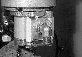
4.Remove the two mounting bolts securing the lift pump to the lift motor. See Figure7-163.
5.Carefully separate the pump from the motor, taking care not to damage the toothed spline.

6.Install the hydraulic fittings on the new lift pump.
8.Carefully mate the new lift pump spline to the lift motor and attach the lift pump to the lift motor with the two mounting bolts.
9.Replace the filter on the manifold. See Figure7-164.
7.Apply molybdenum anti-seize compound (P/N 990-638) to the mating surfaces of the lift motor spline and the pump.
10.Connect the hoses.
11.Insert the drain plug in the drain hose and fill the hydraulic reservoir with new fluid.
12.Reconnect the battery connector and turn the key switch ON. Test the lift truck operation before returning to service.

13.Bleed the hydraulic system as necessary.
14.Install the tractor covers.
Publication Number: 1043922B, Revised: 2 Sept 2015


