2 minute read
Model 5200 High-Level Orderpicker
from Raymond 5200 High-Level Orderpicker Lift Truck Maintenance Manual SN 1000 and up - PDF DOWNLOAD
Section 7.Component Procedures
Hydraulic Components Side Cylinder
Side Cylinder
Use extreme care whenever the lift truck is jacked up. Never block the lift truck between the telescopic and the floor. Keep hands and feet clear from vehicle while jacking the lift truck. After the lift truck is jacked, place solid blocks beneath it to support it. Do not rely on the jack alone to support the lift truck. See “Jacking Safety” on page2-8.
NOTE: Use a mirror to enable you to see the snap ring at the bottom of each cylinder housing in the following procedures.

Remove
1.Elevate the platform far enough to access the tubing that connects to the bottom of the lift cylinder but not far enough to extend the side cylinder. Block the carriage in place.
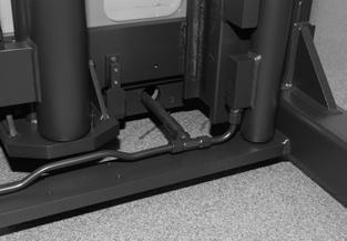
2.Remove the tubing from the bottom block on the cylinder that is to be removed. Cap both the tubing and the fitting to the lift cylinder.
4.Remove the bolt in the top of the lift cylinder that connects it to the bracket on the telescopic.
5.Elevate the platform until it clears the ram assembly enough to allow removal.
6.Block the carriage and telescopic.
7.Remove the snap ring from the bottom of the cylinder. See Figure7-168.
3.Unblock and lower the platform to the floor.

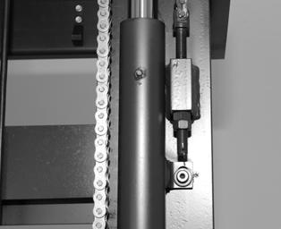
8.Remove the bolt that attaches the cylinder housing to the main frame of the lift truck. See Figure7-169.

9.Remove the lift cylinder from the lift truck.
Publication Number: 1043922B, Revised: 2 Sept 2015
Section 7.Component Procedures
Model 5200 High-Level Orderpicker
Side Cylinder Hydraulic Components
Installation
1.Install the cylinder in the lift truck.
2.Install the bolt that attaches the cylinder housing to the main frame of the lift truck.
3.Install the snap ring on the bottom of the cylinder housing. See Figure7-168.

4.Unblock the mast an d lower the platform far enough to collapse the other outer cylinder but still have access to the fitting at the bottom of the cylinder.
5.Block the platform in place. Connect the tubing to the bottom of the cylinder.

6.Unblock and lower the platform to the floor. Install the bolt in the top of the lift cylinder that connects it to the bracket on the telescopic.
7.Bleed the hydraulic system. See “Bleeding the Hydraulic System” on page7-88.
8.Lift and lower the carriage completely to check the lift function.
Cushion Service
1.Remove the cylinder from the lift truck. See “Side Cylinder” on page7-89.
2.Remove the snap ring and wiper. See Figure7-170.
4.Pull the piston until the piston stop pushes retaining ring, packing, and adapter out of the cylinder. See Figure7-170.
5.Pull the piston out of the housing. Place the piston on a cushioned stand. Do not damage piston surface.
6.Push the cushion into the piston at the base of the piston.
The cushion is under extreme pressure. Keep pressure on the cushion when removing the items in the next step. Failure to do so could cause injury from projectile parts.
7.Remove the snap ring and the retaining ring. See Figure7-171.
8.Release the pressure on the cushion and pull the cushion out of the piston. See Figure7-171.
9.Remove the spring. See Figure7-171.
Publication Number: 1043922B, Revised: 2 Sept 2015


