5 minute read
Model 5200 High-Level Orderpicker
from Raymond 5200 High-Level Orderpicker Lift Truck Maintenance Manual SN 1000 and up - PDF DOWNLOAD
Section 7.Component Procedures
Drive and Brake Brake
Various shims and spacers are available for adjusting the air gap.
Adjustments can be made without removing the brake coil assembly from the lift truck.
Shims and spacers should be added or removed equally at each of the three assembly screws. See Figure7-108.
The air gap should be uniform (within 0.005 in. [0.127 mm]) when measured at various points around the brake.

When the correct air gap is obtained, torque the assembly screws to 9 ft. lbs. (12 Nm).
Brake Friction Plate (Rotor)
Replace the brake friction plate if the thickness is less than 0.236 in. (6 mm). See Figure7-108.
Disassembly
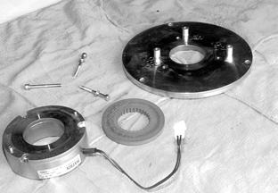
1.Remove assembly screws (3) from the brake. See Figure7-109.
NOTE: Keep track of the number and thickness of shims under each spacer.
2.Lift the coil assembly off the friction plate.
3.Remove the old friction plate.
Inspection
Check the mounting plate and the brake coil assembly for signs of wear. If either part has severe gouging or wear exceeding 0.010 in. (0.25 mm), replace the brake.
Publication Number: 1043922B, Revised: 2 Sept 2015

Section 7.Component Procedures
Model 5200 High-Level Orderpicker
Brake Drive and Brake
Assembly
1.Install a new friction plate in the center of the mounting plate. See Figure7-110.

2.Install a 0.020 in. (0.508 mm) shim between a 0.709 in. (18 mm) spacer and mounting plate on each assembly screw. See Figure7-110.
3.Place the brake coil assembly on top of the friction plate. See Figure7-110.
4.Tighten the assembly screws (3). See Figure7-109.
Assembly Screws
Shims
Brake Coil Assembly
5.Check the air gap. See “Brake Air Gap Adjustment” on page7-52. 77k10123s
Mounting Plate Friction Plate
Publication Number: 1043922B, Revised: 2 Sept 2015
Section 7.Component Procedures
Battery Procedures
Battery Procedures
Before working on the battery, review Battery Safety, beginning on page2-5. Batteries for this lift truck weigh between 920 and 2000 lb. (418 to 908 kg). Use extreme care during replacement. Use a suitable battery moving device or hoist for lifting. Do not extend a battery more than 1/3 of its length outside the battery compartment without being attached to a battery-moving device.
NOTE: The distance from the floor to the top of the battery rollers is 12.25 inches (31.12 cm).
Battery Connector/Cables Location
The battery connector is installed at the front-right of the tractor, above the battery.
Removal, Replacement, and Installation
The cables to either half of the connector have a lip on their forward end. This lip snaps over a spring-loaded retainer that is part of the connector.
Model 5200 High-Level Orderpicker
Electrical Components
When replacing battery cable ends, remove only one end at a time from the connector, to avoid the cable ends touching and causing a short circuit. Do not allow the metal cable end to touch the battery. Use insulated tools and avoid contact with battery case or cable ends.
1.To remove a cable from the connector, you must push this retainer down while pulling the battery cable towards the rear and out of the connector. See Figure7-112.

2.Do not attempt to repair battery cables by crimping new terminals. Replace the cable.
Battery Exterior Cleaning
1.Read, understand, and follow procedures, recommendations and specifications in the
7-56
Publication Number: 1043922B, Revised: 2 Sept 2015 battery and battery charger manufacturer’s manuals. of 1 lb. (0.45 kg) of baking soda added to 0.5 gal. (1.9 liters) of hot water.
7.Use a brush with flexible bristles to clean the entire top of the battery with the soda solution. Wait until all foaming stops, indicating that the battery exterior is neutralized.
8.Rinse the battery with clean water.
9.Dry the battery completely before reinstalling it.
2.Wear personal protective equipment. See “Battery Safety” on page2-5
3.Turn the key switch OFF and disconnect the battery connector. Remove the battery from the lift truck.

4.Inspect the battery cables to make sure they are not frayed or loose. Inspect the battery connector to make sure there is no foreign material inside the connector. Make sure the filler plugs are tight and the vent holes in the filler plugs are open.
10.Reinstall the battery in the lift truck, using a suitable battery moving device. Reconnect the battery connector.
Testing, Charging, and Maintenance
For information on testing, charging, and maintaining your lift truc k battery, consult the battery manufacturer’s specifications and instruction manual.
NOTE: Never plug the battery charger into the lift truck. This severely damages the lift truck’s electrical system. Plug the charger only into the connector from the battery.
5.Keep the top of the battery clean and dry. Corrosion, dust, and moisture provide a conducting path to short-circuit cells or create shorts to ground.
NOTE: Do not clean the top of the battery with the soda solution while it is installed in the lift truck. Water can seep into the electrical components and cause serious damage.
6.Wash dirty batteries (or any that have had electrolyte spilled on them) with a solution
Battery State-of-Charge
Battery State-of-Charge (BSOC) is a feature that monitors and remembers the charge level of the battery connected to the lift truck and prevents excessive discharging of that battery. Operating a lift truck using a discharged battery can damage both the battery and the electrical components of the lift truck. See page5-4 for a detailed description of how BSOC works and the procedure for setting BSOC Cutout.
Publication Number: 1043922B, Revised: 2 Sept 2015
Section 7.Component Procedures
Model 5200 High-Level Orderpicker
Power Cables
Check power cables for:
•evidence of overheating
•burned spots in the cable
•nicks in the insulation
•damaged or overheated terminal lugs
•damaged mounting hardware or brackets
Replace damaged cables or mounting hardware as necessary.
Power cables are marked on the terminal lug with the location where they belong. If the marking is missing or is not readable, remark the cable with the correct information.
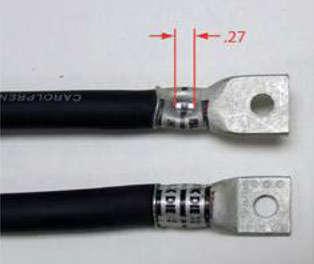
NOTE: Terminal lugs may be replaced in the field using the appropriate crimping tools. Crimping tool, lugs, and heat-shrink are available through the Parts Distribution Center. Failure to use correct cables, terminal hardware, and torque values can result in overheating and damage to components.
Power Cable Repair
Traditional lug crimping techniques for power cables on DC motors may not meet the higher current requirements of AC motors. Use Manual Crimp Tool (P/N 1069861) when crimping power cables for all AC motors. This tool may also be used to repair power cables for DC motors.
1.Remove the bad cable(s).
2.Using the removed cable(s) for reference, cut an appropriate amount of replacement cable of the same gauge.
3.Set the adjustment screw on the manual crimp tool head to match the cable gauge.
4.Strip the cable jacket to fit the terminal to be crimped. Refer to Table7-4 and Table7-5
Table 7-4.Cable Jacket Strip Length - Short Barrels
AWG Lug P/N Strip Length
1/01002215/001-00411/16 in. (17 mm)
2/01002215/005-00813/16 in. (21 mm)
3/01002215/009-0121 in. (25mm)
4/01002215/013-0151-1/16 in. (27 mm)
Table 7-5.Cable Jacket Strip Length - Long Barrels
AWG Lug P/N Strip Length
1/01002217/001-003
2/01002217/004-006
3/01002217/007-009
1-9/16 in. (40 mm)
4/01002217/010-0111-11/16 in. (43 mm)
5.Insert the cable into the terminal.
6.Place the cable and terminal into the tool die and crimp. Refer to Figures 7-114 and 7-115

Publication Number: 1043922B, Revised: 2 Sept 2015
Power Cables Electrical Components 7-58 a.For short barrels, use 1.75 in. (45 mm) of tubing. Apply 1 in. (25 mm) over the jacket extending 0.75 in. (19 mm) over the barrel. b.For long barrels, use 2.5 in. (64 mm) of tubing. Apply 1 in. (25 mm) over the jacket extending 1.5 in. (38 mm) over the barrel.
7.Apply heat-shrink tubing (P/N 611-035) to the terminal after crimping.

Publication Number: 1043922B, Revised: 2 Sept 2015
Section 7.Component Procedures
Model 5200 High-Level Orderpicker
Motors (General) Electrical Components
Motors (General)
Motor Cleaning
Never use a chemical solvent to clean a motor, as it can carry carbon dust to inaccessible areas and cause shorts within the motor.
Cleaning a motor with solvents requires complete disassembly and drying, and should only be performed by an authorized motor repair shop.
Periodic cleaning is essential to prevent overheating and shorts-to-frame. To clean a motor correctly:
1.Wear safety glasses or goggles to protect your eyes from dust and debris.
2.Using an OSHA approved air nozzle, use clean, dry, low pressure (30 psi or 207 kPa or 2.1 kg/cm2) compressed air to blow carbon dust and other foreign matter from:
•Motor housing
•Brush holders
•Commutator
•Field and armature windings (if accessible)
Motor Brushes
Location
•Traction motor brushes, see Figure7-118.
•Lift motor brushes, see Figure7-119
•Steer motor brushes, see Figure7-120.
Publication Number: 1043922B, Revised: 2 Sept 2015


