1 minute read
Model 5200 High-Level Orderpicker
from Raymond 5200 High-Level Orderpicker Lift Truck Maintenance Manual SN 1000 and up - PDF DOWNLOAD
Section 7.Component Procedures
Mast Section Load Wheels
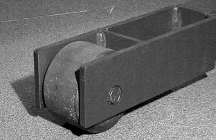
Load Wheels
Use extreme care whenever the lift truck is jacked up. Keep hands and feet clear from the vehicle while jacking the lift truck. After the lift truck is jacked, place solid blocks beneath it to support it. Do not rely on the jack alone to support the lift truck. See “Jacking Safety” on page2-8.
1.Raise the operator platform approximately 1 ft. (0.3 m) from the floor. Place a 4 x 4 in. (100 x 100 mm) block across the top of the baselegs underneath the platform.
2.Turn the key switch OFF and disconnect the battery.
3.Jack up the baseleg high enough to clear the load wheel from under the baseleg. Place a block under the baseleg.
4.Remove the snap ring from the axle. See Figure7-219.
5.Drive out the axle. The load wheel falls out of the baseleg. See Figure7-219.
6.Replace the load wheel assembly.

7.Drive the axle back through the wheel and baseleg.
8.Install a new snap ring.
9.Remove the blocks.
Publication Number: 1043922A, Revised: 2 Sept 2015 7-121
Section 7.Component Procedures
Model 5200 High-Level Orderpicker
Skid Pads
Skid Pads Location
There are two skid pads on each lift truck.
Inspection
1.Check the clearance between each skid pad and the floor.
2.If clearance is more than 3/4 inch (19.1 mm) on either side, replace the skid pad. See procedure below.
Use extreme care whenever the lift truck is jacked up. Keep hands and feet clear of from the vehicle while jacking the lift truck. After the lift truck is jacked, place solid blocks beneath it to support it. Do not rely on the jack alone to support the lift truck. See “Jacking Safety” on page2-8.
Replacement
Weld a new skid pad inside the worn skid pad. Clearance from the floor should be 3/4 inch (19.1 mm). See “Welding Safety” on page2-13.
Publication Number: 1043922A, Revised: 2 Sept 2015
Mast Section 7-122


