OPERATING INSTRUCTIONS
Removal
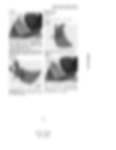
STEP 9
STEP 2
CK97A002
Place the switch in the locked position. See “Quick Coupler locking/unlocking control switch” in the “Controls/Instruments/Accessories” Section. CD98D041
Remove the split pin and retaining pin. TRIM THIS EDGE
IMPORTANT: Check that the Quick Coupler is properly attached to the tool linkage pins.
STEP 3
STEP 10
CK97A002 CD98C018
Install the retaining pin and the split pin. IMPORTANT: The retaining pin and split pin must be in place.
Place the switch in the unlocked position. See “Quick Coupler locking/unlocking control switch” in the “Controls/Instruments/Accessories” Section.
147
TRIM THIS EDGE RIGHT PAGE
Template Name: OM_1_col Template Date: 1994_04_29
Place the tool on flat, level ground.
Alt= to hide template information Alt+ to display template information
STEP 1


