2 minute read
MACHINE OPERATION


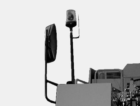
ROTARY BEACON (specific to certain countries)
The rotary beacon must be installed for road travel. See “Road travel” in the “Job Site and Road Operation” Section.
STEP 1 STEP 3
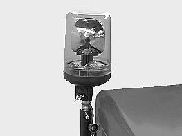
PG02700 Remove the protective cap from the end of the tube located at the top of the cab.
STEP 2
PG02702
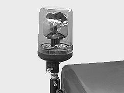
Tighten the wing nut. The rotary beacon is turned on and off by the switch on the instrument panel. IMPORTANT: The rotary beacon must be on when travelling. IMPORTANT: When removing the rotary beacon, make sure to put the cap back on the end of the tube. NOTE: To replace the bulb see “Replacing a bulb” in the “Electrical System” Section.
PG02702 Place the rotary beacon on the end of the tube. TRIM THIS EDGE
109
TRIM THIS EDGE RIGHT PAGE
Template Name: OM_1_colTemplate Date: 1994_04_29
Template Date: 1994_04_29Template Name: OM_1_col
TRIM THIS EDGE
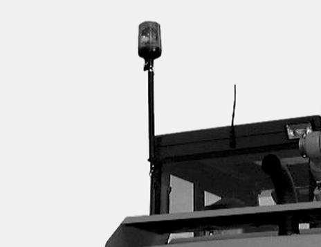
CD99N041 Some machines are equipped with a rotary beacon on a bracket which is attached to the fuel tank.
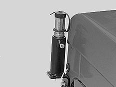
CD99N042 Some machines are equipped with a rotary beacon fitted with an extension which is used to increase the height of the rotary beacon.
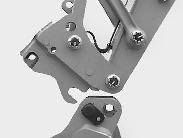
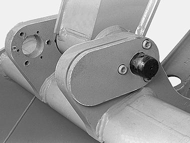
MAXIMUM OPENING RANGE AND MAXIMUM FORCE Backhoe bucket Quick Coupler (optional)
The linkage position of the bucket and the dipper can be adapted to suit the work to be done. The linkage position of the Quick Coupler and the connecting rod can be adjusted to suit the work to be done.
2
2
1 1
PH07809 Maximum opening range position (1). Maximum force position (2). NOTE: During road travel, the backhoe bucket must be in the maximum force position. See “Road travel” in the “Job Site and Road Operation” Section.
CD98C019 Maximum opening range position (1). Maximum force position (2). To change the linkage point, remove the pin, operate the bucket cylinder control to bring the connecting rod to the other linkage point and install the pin.
110
TRIM THIS EDGE LEFT PAGE