1 minute read
ELECTRIC TRAVEL


STEP 9
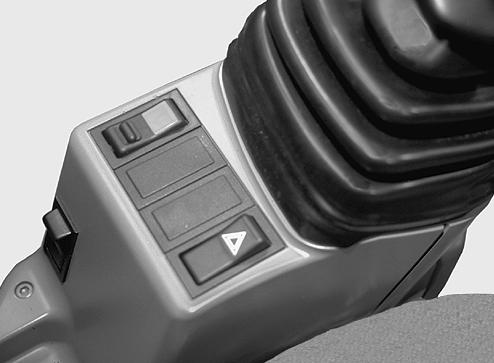
CK97A002 Place the switch in the locked position. See “Quick Coupler locking/unlocking control switch” in the “Controls/Instruments/Accessories” Section. IMPORTANT: Check that the Quick Coupler is properly attached to the tool linkage pins.
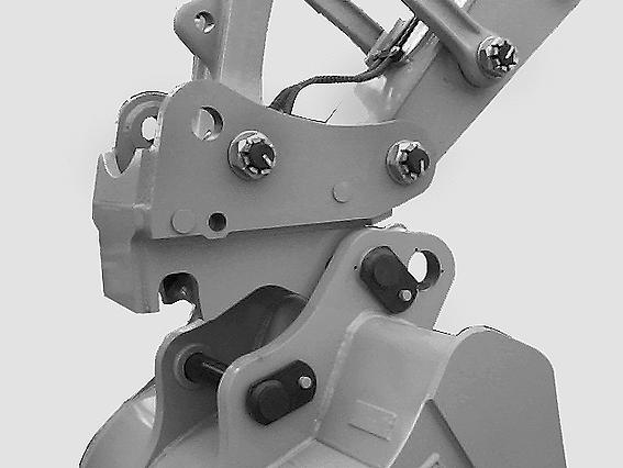
STEP 10
CD98C018 Install the retaining pin and the split pin. IMPORTANT: The retaining pin and split pin must be in place.
Removal
STEP 1
Place the tool on flat, level ground.
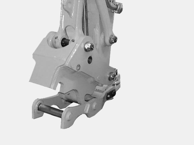
STEP 2
CD98D041 Remove the split pin and retaining pin.
STEP 3
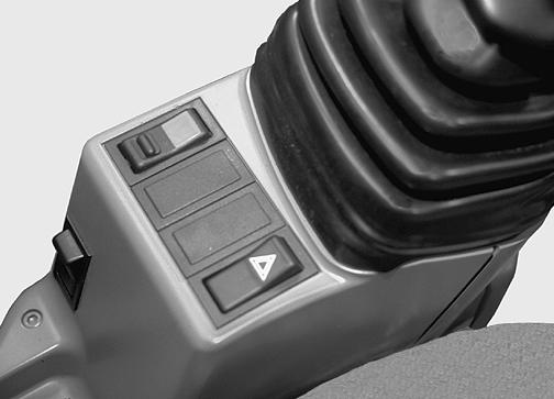
CK97A002 Place the switch in the unlocked position. See “Quick Coupler locking/unlocking control switch” in the “Controls/Instruments/Accessories” Section. TRIM THIS EDGE
147
TRIM THIS EDGE RIGHT PAGE
Template Name: OM_1_colTemplate Date: 1994_04_29
Template Date: 1994_04_29Template Name: OM_1_col
TRIM THIS EDGE
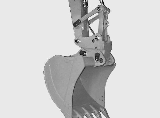
STEP 4
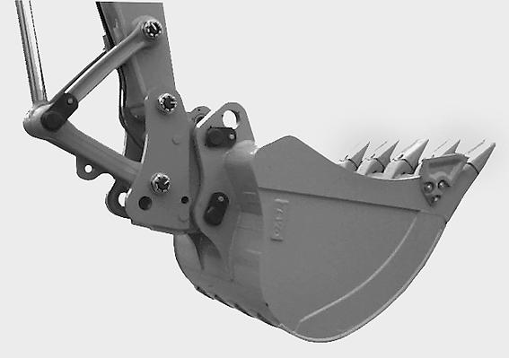
CD98C017 Wait for five to ten seconds to allow the hook to retract. Operate the bucket control lever so as to disengage the pin.
STEP 5
Loader application
CD97H002 The Quick Coupler allows you to reverse your buckets to serve as a loader.
Clamshell installation
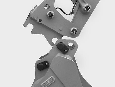
STEP 1
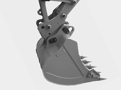
CD98C020 Operate the dipper control lever so as to disengage the bucket.
CD00D001 Mount the clamshell adaptor on the quick coupler. See “Tool installation and removal using the quick coupler”. Make sure the clamshell adaptor is correctly positioned with the linkage pin lug on the left-hand side.
148
TRIM THIS EDGE LEFT PAGE