Click on the handle of a rotary switch and turn it right until the lock bar switch is not fully sink in deeper (Figure 7.21).
Fig. 7.21. Latch panel swi-lei moves up or down at in vorachivanii handle Rotation re-klyuchatelya: 1 - lever, 2 - retainer Hold the handle in this position, insert the panel in the landing slot, and turn the knob to the left to lock the panel. Check the operation of the switch in all positions and is mounted panel
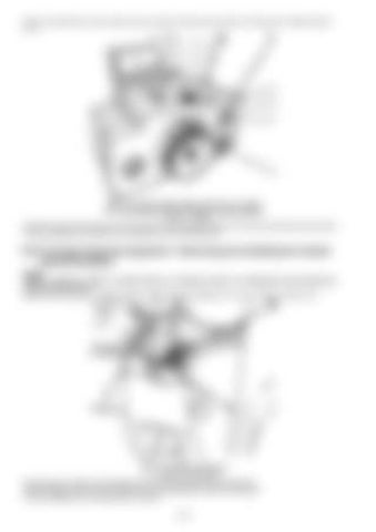
6.23 On-board electrical equipment - Removing and installing the module gearshift paddles NOTE Paddles Switches -stalled in Contact block on wheel-ing column. To withdrawal levers should pre remove contact block. Slide the lever toward the anther edge grip, insert the punch diameter of 1.5 mm as shown in Figure 7.22.
Fig. 7.22. Setting knockout: 1 - anther 2 - hammered Squeeze punch retainer and separate from the lever assembly of the contact block. When installing, enter the lever assembly of the contact block and press it into place. Further installation is in reverse order of removal
324


