3 minute read
1.29 Driving with a trailer


If the trailer coupling is installed on the car manufacturer, it is taken into account automatically. When riding with the trailer parking pilot is automatically disabled when installing the trailer plug the cable into the slot.
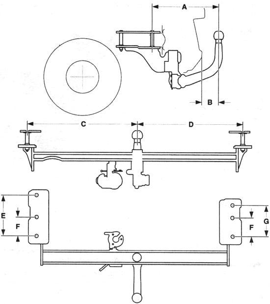
NOTE When Installation rear boots, such for bike, remember, those they mounted sensors near "Parking pilot and may break functioning tion system. Installation the size of golf - the coupling devices with removable ball drawing «Limousine»
All these dimensions correspond to the trailer coupling trailer, mounted by the manufacturer.
Size Value, mm
A 342.9 In 83 With 513.4 D 488.6 E 211.4 F 94.3 G 160
NOTE Use only admitted to this Vehicle tyago in - coupling device. At cars with engined Z 20 LEH assembly Pull - the coupling not allowed.
Mounting dimensions trailer coupling with removable ball of «Caravan» All these dimensions correspond to the trailer coupling trailer, mounted by the manufacturer.
NOTE Use only admitted to this Vehicle tyago in - coupling device. At Opel Astra cars with engined Z 20 LEH assembly Pull - the coupling not allowed.
Size
A In
Meaning, MM
84.0 570.0
With D E 515.0 93.5 173.0
F G 307.6 158.0
H 292.6
Placing ball bearing trailer coupling
In the model of "Limousine» spherical bearing in the cover secured in the cargo box luggage fastening straps. In the model «Caravan» spherical bearing fixed fastening straps to the luggage compartment in the recess for the spare wheel.
Installation of ball bearing
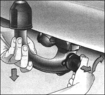
To release the connector and slide it down. Remove the cap from the opening for ball bearing and place them in the trunk (Fig. 1.231). Check the position of a ball bearing. Red markings on the swivel bracket should be directed towards the white markings on the ball anvil. Between the swivel bracket and ball support should be a gap width of about 6 mm (Fig. 1.232). Stopper is inserted into the lock and is in position 1 (Fig. 1.232). Otherwise, you must hold down ball-bearing before installing casing couplings. Unlock the ball as transferring detent in position 1 (Fig. 1.232). Pull the swivel bracket and turn it into the elongated position all the way to the right (Fig. 2.233).
Install ball bearing
Insert ball-bearing sandwiched into the body and sleeves with force fed up to its fixation (Fig. 2.234). Swivel arm themselves back in position and again adjacent to the ball support.
NOTICE When installing the ball bearing does not touch the swivel bracket, because at the time of fixation he can injure his hand.
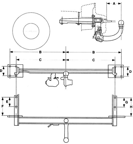

Fig. 1.230. Ball reliance Pull - clasped-tion device
Closed ball as setting the stopper in position 2 (Fig. 1.232). Remove the stopper and press the security tab (Figure 2.235). After the closure of a ball bearing swivel bracket is no longer stretched.
Test after Installation
Check the correctness of mounting a ball bearing.
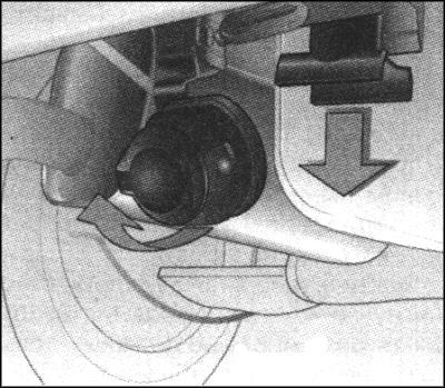
Fig. 1.231. Exemption connector tyago of - coupling device
The green markings on the swivel bracket should be directed towards the white markings on the ball anvil. Between the swivel bracket and ball support should not be any backlash. Ball bearing tightly fixed in the clutch housing. Ball bearing must be locked.
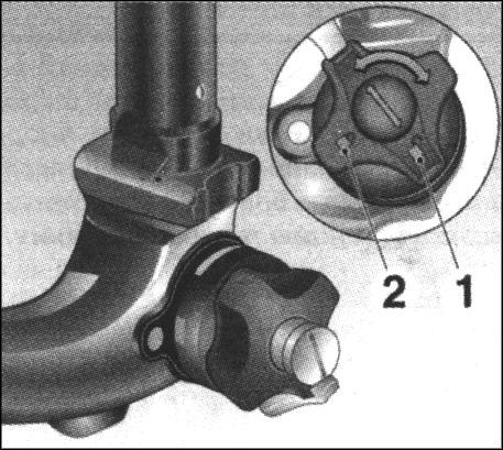
Fig. 1.232. Markings on the swivel bracket and the ball of
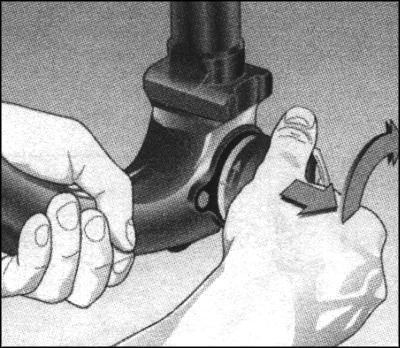
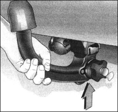
Fig. 1.234. Install ball bearing
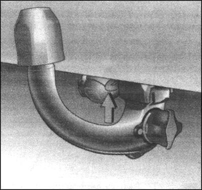
Fig. 1.235. Security tab
NOTICE Horseback with trailer allowed Toll-to with correctly clamped Sharo-ing support. If ball support right consolidate not not necessary contact for Pomo-schyu on station maintenance.
Eyelet for traction cable For trailers with a brake hook tether for the eyelet (arrow in Figure 1.235).
Dismantling ball support
Unlock the ball as turning the stopper in position 1 (see Fig. 1.232). Pull the swivel bracket and turn it all the way to the right. Pull the ball bearing housing clutch down and put it in a duffel compartment in the trunk (Fig. 1.236).