1 minute read
7.18 Removal and installation of exterior side door handles


Fig. 8.22. Disconnecting traction door lock (On example castle back side door):
1 - Lock clamp, 2-pull door lock; 3 - lining the back of the door lock Remove the 3 mounting bolts on the rear end wall and separate the door lock from the door frame. At the front door, disconnect traction cylinder door locks. Remove the lock from the frame. Release the flexible pull the holder of the door lock and remove the core thrust of the rotary lever locking button (Figure 8.23).
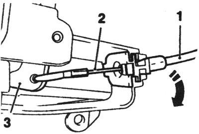
Fig. 8.23. The core flexible traction to a turning lever HGS button:
1 - a flexible rod, 2 - core, 3 - turning the lever Installation is performed in reverse order of removal. Do not forget to replace the liner. Do not shut the door, test the locking mechanism.
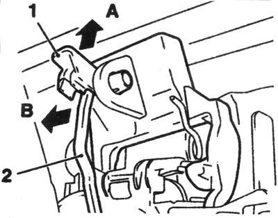
Open the door. On models equipped with the system Open & Start, remove the door trim and disconnected the wiring connector automatic recognition. Using a plastic wedge remove the plug holes on the rear end wall of the door, pull the outside handle of the door and turn the locking screw counterclockwise until it stops - handle should fix dragged into position (Fig. 8.24).

Fig. 8.24. Commit outer pen in dragged position (arrows B):
1 - outdoor pen, 2 - core, 3 - locking bolt Remove the key cylinder with the body of the door.
NOTE On front Passenger and posterior them side doorway cylinder lock it.
The order lifting the door handle is shown in Figure 8.25. Installation is performed in reverse order of removal. The locking bolt to rotate in a clockwise direction, with the need to hold in the situation dragged outside door handle and door lock housing from being rotated.


