7 minute read
SAC


NOTICE Use only brake fluid DOT 4.
The hydraulic clutch is pumped only "bottom", that is pumped through the valve. For this purpose the device is used to remove air from the hydraulic brakes.
NOTICE Manual pumping not allowed. Follow production Ying-tion at use aspirations STVA for delete air of Tormo-call. Device for delete air to ha of Brakes should ensure pressure approximately 2 bar. Hardware Installation
Connect the device to remove air from the hydraulic drive. To do so, attach the adapter device for removing air from the brakes to Backa hydraulic brake system. Install special tool IMC-6174-2 on the adapter. Lower the end of the hose into a suitable container. Remove the valve cap from the valve pumping and attach a special tool IMC-6174-1 to the valve pumping (Fig. 3.2). Remove air from the clutch. Turn on the device for removing air from the hydraulic drive. Open the valve pumping (2-3 overleaf). Pump to release the brake fluid without bubbles. Close (by hand) valve pumping.
Removing device
Unplug the device for removing air from the hydraulic drive. Disconnect the adapter device for removing air from the hydraulic drive.
NOTICE Must follow following operations for fill gall-ment pipeline Carter co-shy Transmission Desktop cylinder clutch. When pumping certifying believe that tank hydraulic brake system filled.
Remove air from the discharge line of the working cylinder clutch. Install special tool IMC-6174-2 on MCM-6174-1 on the valve pumping, lower the free end in a suitable container Press and hold the clutch pedal. Open the valve pumping. Open the valve before pumping air and / or a mixture of air / brake fluid. Close (by hand) valve pumping. Slowly release the clutch pedal and wait approximately 5 seconds. Repeat the procedure four times. Tighten the valve point pumping 5 N-m. Remove the special tools IMC-6174-1 and IMC-6174-2. Remove the cap from the valve pumping. Fill the tank hydraulic clutch brake fluid to the mark "MAX". Close the tank hydraulic brake system. Check the opening pressure of the clutch pedal. Check to include all gear with the engine running and clutch depressed.
NOTE Make trial trip, something would ensure clear work si-tem Clutch and inhibition. Travel spend with different velocities and frequent switch-em transfers to reach work-chih temperatures.
2.3 Clutch - Removal, inspection and installation of hard plates and the driven clutch plate (without SAC)
NOTE To prevent damage to the petals spring thrust plate use a special device KM-6263 after removal and installation. NOTE Note the different length brackets for joining the CM 6263 at lowering engine block. Withdrawal
Remove the gearbox
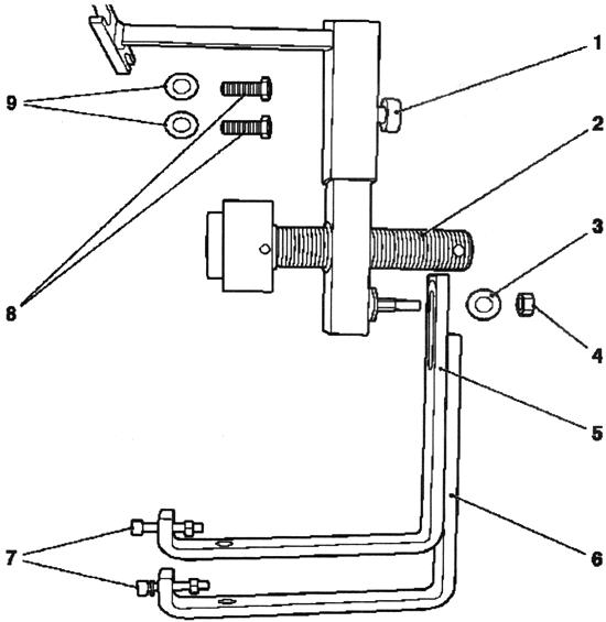
Fig. 3.3. Gadgets for withdrawal and Installation stubborn Plates and slave disc clutch: 1 - pin 2 - retractors, 3 - Disc 4 - nut; 5 - KM-6263-4 (short arm), 6 - KM-6263-5 (long arm); 7 - lower bolt engine block; 8 - upper bolt engine block; 9 - Puck
NOTE Special KM-6263 device can is attached only to block engine and not to oily pallet.
Attach a special device KM-6263 to the engine block and tighten the 4 bolts (arrows in Figure 3.4).
NOTE Not tighten bolts.
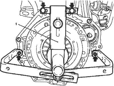
Fig. 3.4. Accession -adapted-tion:
1 - adaptation Attach a special device KM-6263-30 (4) to the alignment fixture (Figure 3.5).
Transmission Aligning arbor
F13 CM-6263-21 F17 + CM-6263-21 F23 CM-6263-22
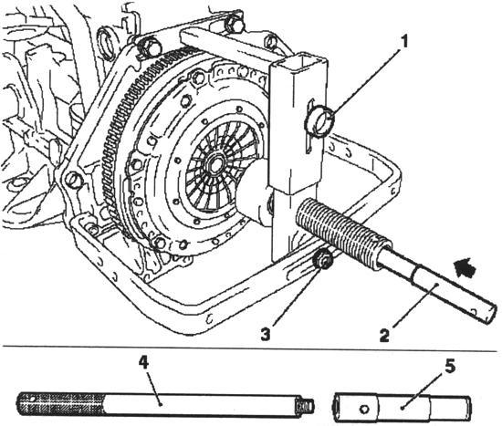
Fig. 3.5. Setting special accessories and alignment mandrel: 1 - pin 2, 4 - a special device KM-6263-30; 3 - nut, 4 - aligning arbor
Attach a special device KM 6263. Align special device KM-6263 with the center. Set alignment mandrel with a special device KM-6263 KM-30 through 6263 in the drive clutch and the crankshaft (center). Tighten the bolt and nut. Tighten the 4 bolts special device KM-6263 to the engine block (Fig. 3.5). Free slave clutch disc. Set a special device KM-6263 so that it was situated opposite the petals spring thrust plate (Fig. 3.6). Turn special device KM-6263 clockwise to the limiter. Remove the thrust plate to the flywheel. 6 Loosen the mounting bolts (arrows in Figure 3.7).
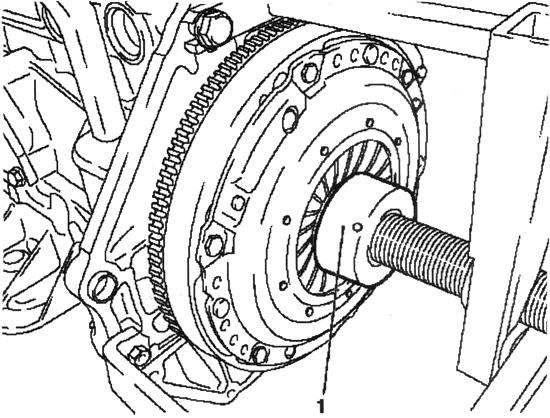
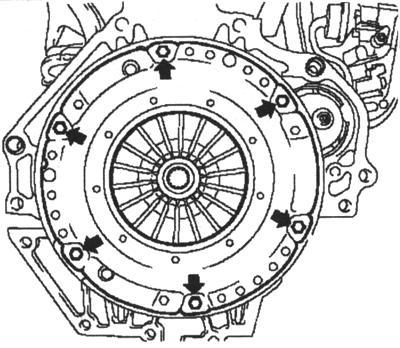
Fig. 3.7. Bolts mounting the flywheel
NOTE On Figure 3.7 shows traction without special KM-6263 and accessories alignment mandrel.
Remove the thrust plate and clutch disc. Turn special device KM-6263 counter-clockwise until the limiter and pull the mandrel alignment with a special device KM-6263-30.
Test
Check thrust plate and driven clutch disc wear. Replace if necessary.
NOTE The clutch labor-contaminated products (oil, detergent, etc.) should be replaced. Check the slave clutch disc for damage and wear products on the hub and replace if necessary. Do not empty the thrust plate and driven clutch disc high-pressure cleaners or washing machine.
Check the friction surface of the flywheel on the absence of cracks, burnt and the wear surface. Check the condition of the friction linings and clutch slave drive if they have traces of oil or mechanical damage, replace the slave drive. Check the thickness of the lining driven clutch plate, with the help of vernier calipers. Overlays should speak over the heads of rivets not less than 0.3 mm (Fig. 3.8).
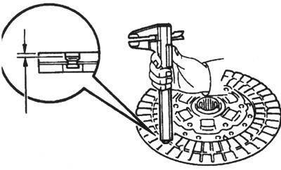
Fig. 3.8. Measurement of friction linings slave clutch plate
If the thickness of the lining is less than the permissible or rivet heads are close to the working surface, replace them or slave drive clutch. Check that the springs were not broken and they are no cracks. Check on the lack of wear slots in the hub clutch discs. Replace clutch disc to the shaft of the gearbox (Figure 3.9).
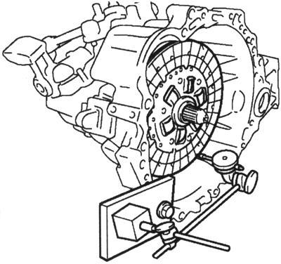
Fig. 3.9. Installing slave drive clutch to the shaft of the gearbox
Slave clutch disc should be easily and smoothly slide in the slots of the primary shaft of the gearbox.
NOTICE If conducted replacement slave drive adhesion to per-ndo and bearing clutch.
Using a clock-type indicator, check the pulse of the disc clutch. Minimal beat: 0,8 mm. Using vernier calipers to check the depth and width of wear petals diaphragm spring (3.10).
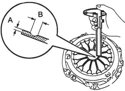
Fig. 3.10. Measuring the depth and width of wear Petal diaphragm spring
Maximum: A (Depth): 0,5 mm B (Width): 6,0 mm
NOTE Minor damage to the friction surface can remove the fine-grained sand boom goy, but in case of any doubt about the condition of the pressure plate must be replaced by new.
Using a clock-type indicator, check the pulse of the flywheel (Fig. 3.11).
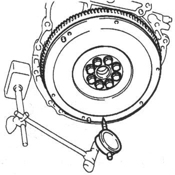
Fig. 3.11. Measurement beats Flywheel
Maximum beat: 0,1 mm Rotate bearing clutch hand, applying force in the axial direction, check the clutch bearing (Fig. 3.12).
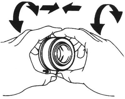
Fig. 3.12. Check bearing turned off-cheniya Clutch
NOTE In bearing laid lubrication calculated on all term exploitation, such , the addi-cen Grease not required. In case necessary, replace bearing off adhesion.
If you install new parts, be sure to find out what pressure plate and slave drive is required for the designation of the engine and its number, to avoid error. If you set the former in the clutch components, they must first check. Before installing the new pressure plate corrosion protective grease must be removed only at the working surface. In other places, to remove grease in any case is not recommended, because it can significantly reduce the lifetime of adhesion. Make sure the installation of centering pins on the flywheel. Clean the rust on the splines slave drive. Lubricate the teeth of the drive shaft gear box with a thin layer of lubricant MoS2. At stations used for this purpose grease G000100. Then move the slave on the primary drive shaft so that the hub is easily moved about the shaft. Sure to remove excess grease. Apply grease on the contact surface couplings and clutch fork, fork and push rod and fulcrum fork (Figure 3.13).
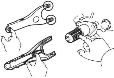
Fig. 3.13. Places Application grease on forks off clutch forks and pusher and point support forks
Apply grease to the splines on the clutch and drive shaft splines. Install clutch fork with bearing clutch in the gearbox.
NOTE After installation, move Fork-ku forward and back for check smoothness movement Clutch release th bearing. Setting NOTE Literal designation «Transmis - sion side » should is drawn to box transmission.
Attach the slave drive clutch and thrust plate to the flywheel. Ottsentriruyte thrust plate and clutch disc alignment mandrel and a special device KM-6263-30 (Fig. 3.14).
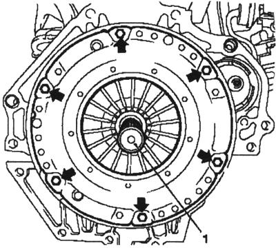
Fig. 3.14. Spigot stubborn plas-slime and CD Clutch: 1 - adaptation of the CM-6263-30
NOTE For visibility Figure 3.13 There-is called clutch without adapted-PRINCIPLES FOR GOOD GOVERNANCE KM 6263.
Tighten the 6 new bolts (arrows in Figure 3.13).
NOTE Not tighten bolts.
Attach the thrust plate to the flywheel. Turn special device KM-6263 clockwise to the limiter. Tighten the 6 bolts fastening point 15 N-m.
NOTE Tighten Bolts crosswise.
Remove special device KM-6263 from the engine block. Turn counterclockwise to remove the limiter and alignment mandrel and KM-6263-30 (Fig. 3.15). Loosen the 4 bolts special device KM-6263 to the engine block. Set the gearbox.


