3 minute read
F13 / F17 / F17 + / F23 / M2O / M32


Remove
Close the tank and disconnect the brake hydraulic supply line from the clutch master cylinder (Figure 3.16). Assemble arising brake fluid.
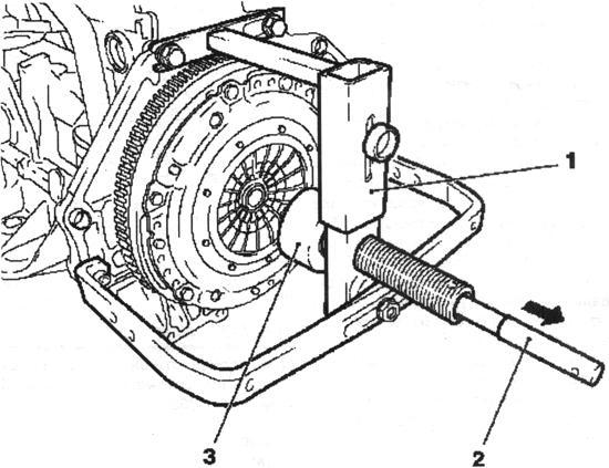
Fig. 3.15. Setting slave CD and stubborn plate: 1,3 - a special device KM-6263-30, 2 - mandrel
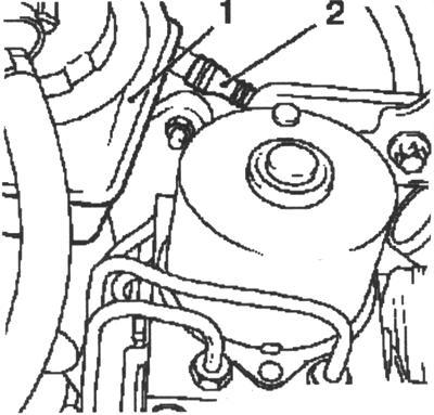
Fig. 3.16. Feeding pipeline and tank stopping hydraulic system:
1 - tank brake hydraulic system 2 - the supply line Close the tank hydraulic brake system of protective cap. Fill the tank hydraulic brake system up to the mark "MAX". Disconnect the mass wire from the battery, disconnect the positive wire from the battery. Remove the strap, loosen the bolt and remove the battery (Figure 3.17).
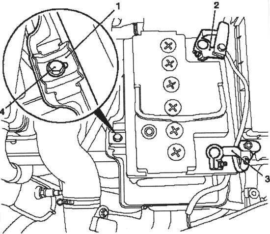
Fig. 3.17. Removing the battery:
1 - spud, 2 - a massive wire; 3 - the positive wire, 4 - bolt Remove the battery support. To do this, remove the cable ties and loosen the 3 bolts fastening (Figure 3.18). Take the expansion tank cooling system places the side. Remove the expansion tank with the support. Disconnect the module anti-lock braking system Disconnect the module anti-lock braking system from the top by unscrewing 2 screws fastening (Figure 3.19).
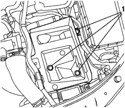
Fig. 3.18. Withdrawal support Battery: 1 - mounting screws
Unleash the conclusion of the bracket. Disconnect the module anti-lock braking system from the bottom. Remove the retaining clamp on the clutch master cylinder. Carefully slide the module anti-lock braking system to the side. 119
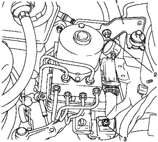
Fig. 3.19. Withdrawal Module antilock system Brakes: 1 - upper bracket, 2 - mounting screws, 3 - bottom bracket
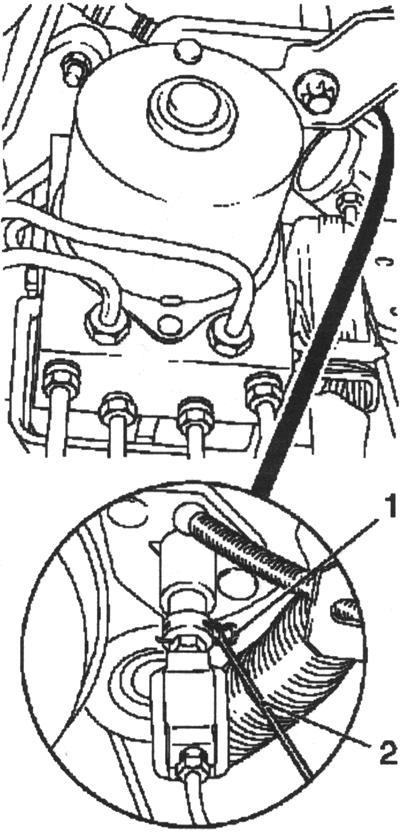
Fig. 3.20. Withdrawal restraint Homa-ta: 1 - holding the collar 2 - Screwdriver
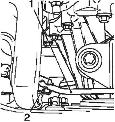
Fig. 3.21. Disconnecting discharge line Executive mecha-ma Clutch:
1 - flow line executive clutch, 2 - Bracket Remove the discharge pipe from the working cylinder clutch. Unlock the retaining collar on the connector working cylinder holding a screwdriver and remove the retaining clamp (Figure 3.22). Disconnect the discharge pipe connections from the working cylinder clutch Remove the flow line of the actuator coupling (Fig. 3.23).
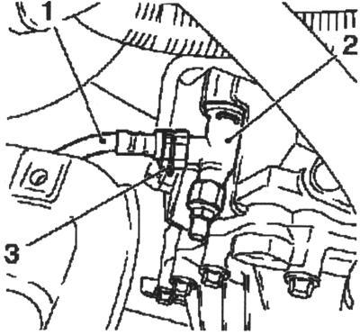
Fig. 3.22. Withdrawal discharge Oil throughput with Desktop cylinder Clutch: 1 - flow line; 2 - jack working cylinder coupling; 3 - retention clamp
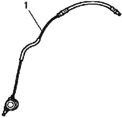
Fig. 3.23. Discharge Pipeline:
1 - Pipeline Check the O-ring on the discharge line (Figure 3.24).
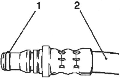
Fig. 3.24. Seal ring Discharge-tatelnogo pipeline: 1-O-ring, 2 - flow line
NOTE Seal ring not may remain in socket Desktop Qi-lindra adhesion. Setting
Install flow line of the actuator coupling to the engine compartment. Install retaining collar. Slightly bend the clamp and set to choke working cylinder clutch. Connect the discharge pipe to the socket of the working cylinder to the crankcase clutch clutch.
NOTE Discharge pipeline long-wives publish click
Attach the flow line in a bracket on the battery. Set delivery pipeline to the executive cylinder clutch. Some bend the clamp and gently insert the module anti-lock braking system with one hand. Attach a clamp holding the master cylinder to the clutch. Insert unagnetatelny pipeline in the clutch master cylinder. Attach the module anti-lock braking system, and tighten the attachment bolt moment 20 Nm. Attach the bracket module anti-lock braking system, and tighten the 2 screws fastening moment 20 Nm. Attach the output to the bracket. Connect the expansion tank cooling system. Install the expansion tank in the bracket.


