JLG 24RS 24RSJ Parts Manual (3121288) - PDF DOWNLOAD (En)

Page 154

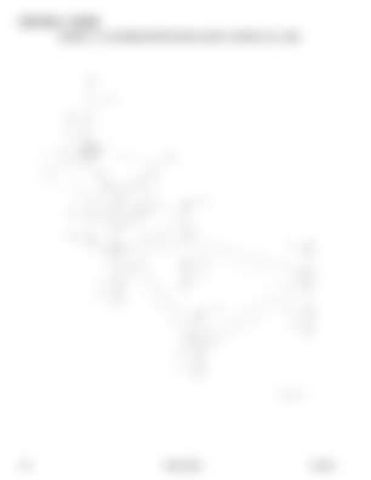
SECTION 4 - BOOM FIGURE 4-11. PLATFORM SUPPORT INSTALLATION - WITHOUT LSS - 24RS

154

24RS_24RSJ

3121288


Turn static files into dynamic content formats.

Create a flipbook

Articles inside

FIGURE 11-1. SPECIAL OPTIONS

2min
pages 380-382

FIGURE 8-36. VALVE HARNESS - 24RS

1min
pages 344-345

FIGURE 10-1. RECOMMENDED SERVICE PARTS STOCK

1min
page 378

FIGURE 8-35. TURNTABLE HARNESS

2min
pages 340-343

FIGURE 8-30. PLATFORM BOX HARNESS - 24RS (SN B300002343 to Present

1min
pages 330-331

FIGURE 8-34. TELESCOPE HARNESS - TOWER BOOM - 24RSJ

1min
pages 338-339

FIGURE 8-29. PLATFORM BOX HARNESS ASSEMBLY - 24RS (Prior to SN B300002343

1min
pages 328-329

FIGURE 8-33. TELESCOPE HARNESS - MAIN BOOM - 24RSJ

1min
pages 336-337

FIGURE 8-31. PLATFORM BOX HARNESS ASSEMBLY - 24RSJ

1min
pages 332-333

FIGURE 8-27. JIB HARNESS

1min
pages 324-325

FIGURE 8-26. GROUND CONTROL PANEL HARNESS - 24RSJ

1min
pages 322-323

FIGURE 8-25. GROUND CONTROL PANEL HARNESS - 24RS

1min
pages 320-321

FIGURE 8-23. EMR2 POWER HARNESS

1min
pages 316-317

FIGURE 8-19. BOOM HARNESS - MAIN BOOM - 24RS

1min
pages 308-309

FIGURE 8-18. BOOM CABLES INSTALLATION - 24RSJ WITH SKYPOWER

1min
pages 306-307

FIGURE 8-16. BOOM CABLES INSTALLATION - 24RS WITH SKYPOWER

1min
pages 302-303

FIGURE 8-17. BOOM CABLES INSTALLATION - 24RSJ WITHOUT SKYPOWER

1min
pages 304-305

FIGURE 8-21. BOOM HARNESS - TOWER BOOM

1min
pages 312-313

FIGURE 8-20. BOOM HARNESS - MAIN BOOM - 24RSJ

1min
pages 310-311

FIGURE 8-15. BOOM CABLES INSTALLATION - 24RS WITHOUT SKYPOWER

1min
pages 300-301

FIGURE 8-4. AC AT PLATFORM RECEPTACLE COMPONENTS - DEALER/CUSTOMER SUPPLIED

1min
pages 278-279

FIGURE 7-9. HYDRAULIC DIAGRAM LIST

1min
page 270

FIGURE 6-11. TELESCOPE CYLINDER ASSEMBLY - 24RSJ

1min
pages 232-233

FIGURE 8-3. AC AT PLATFORM RECEPTACLE COMPONENTS - 220V (ANSI EXPORT SPECS

1min
pages 276-277

FIGURE 8-2. AC AT PLATFORM RECEPTACLE COMPONENTS - 110V GFI (ANSI EXPORT SPECS

1min
pages 274-275

FIGURE 6-10. TELESCOPE CYLINDER ASSEMBLY - 24RS

1min
pages 230-231

FIGURE 6-9. STEER CYLINDER ASSEMBLY

1min
pages 228-229

FIGURE 6-8. MASTER CYLINDER ASSEMBLY - 24RSJ

1min
pages 226-227

FIGURE 6-4. LIFT CYLINDER ASSEMBLY - JIB (SN B300002343 through B300002879

1min
pages 218-219

FIGURE 6-7. MASTER CYLINDER ASSEMBLY - 24RS

1min
pages 224-225

FIGURE 6-3. LIFT CYLINDER ASSEMBLY - JIB - 24RSJ (Prior to SN B300002343

1min
pages 216-217

FIGURE 6-2. LEVEL (PLATFORM SLAVE) CYLINDER ASSEMBLY - 24RSJ

1min
pages 214-215

FIGURE 6-6. LIFT CYLINDER ASSEMBLY - MAIN BOOM

1min
pages 222-223

FIGURE 6-5. LIFT CYLINDER ASSEMBLY - JIB (SN B300002880 to Present

1min
pages 220-221

FIGURE 6-1. LEVEL (PLATFORM SLAVE) CYLINDER ASSEMBLY - 24RS

1min
pages 212-213

FIGURE 5-16. CONTROLLER ASSEMBLY (DRIVE AND STEER

1min
pages 206-207

FIGURE 5-15. CONTROLLER ASSEMBLY (LIFT AND SWING

2min
pages 202-205

FIGURE 5-12. CONSOLE BOX ASSEMBLY (SN B300001540 to Present

1min
pages 196-197

FIGURE 5-10. CONSOLE BOX ASSEMBLY (Prior to SN B300001777

1min
pages 192-193

FIGURE 5-9. PLATFORM CONSOLE ASSEMBLY - 24RSJ

2min
pages 188-191

FIGURE 5-8. PLATFORM CONSOLE ASSEMBLY - 24RS (SN B300001446 to Present

2min
pages 184-187

FIGURE 5-14. CONTROLLER ASSEMBLY (LIFT AND SWING

1min
pages 200-201

FIGURE 5-13. CONSOLE BOX ASSEMBLY (SN B300002343 to Present

1min
pages 198-199

FIGURE 5-7. PLATFORM CONSOLE ASSEMBLY - 24RS (Prior to SN B300001446

2min
pages 180-183

FIGURE 5-1. PLATFORM ASSEMBLY

1min
pages 168-169

FIGURE 5-4. PLATFORM ASSEMBLY – 3FT X 6FT (91.5CM X 1.83M) WITH TRI-ENTRY (3 DROP BARS

1min
pages 174-175

FIGURE 5-3. PLATFORM ASSEMBLY - 3FT X 6FT (91.5CM X 1.83M) WITH TRI-ENTRY (1 GATE / 2 DROP BARS

1min
pages 172-173

FIGURE 5-2. PLATFORM ASSEMBLY - 30IN X 3FT (76CM X .91M) - DROP BAR ENTRY (USA BUILT MACHINES

1min
pages 170-171

FIGURE 4-15. CLAMPS INSTALLATION (BOOM) - 24RSJ

1min
pages 162-163

FIGURE 4-13. PLATFORM SUPPORT INSTALLATION (24RS) - WITH LSS

1min
pages 158-159

FIGURE 4-14. CLAMPS INSTALLATION (BOOM) - 24RS

1min
pages 160-161

FIGURE 4-12. PLATFORM SUPPORT INSTALLATION - WITHOUT LSS - 24RSJ

1min
pages 156-157

FIGURE 4-11. PLATFORM SUPPORT INSTALLATION - WITHOUT LSS - 24RS

1min
pages 154-155

FIGURE 4-10. PLATFORM ROTATOR ASSEMBLY - 24RSJ

1min
pages 152-153

FIGURE 4-8. PROXIMITY SWITCH INSTALLATION - 24RSJ

1min
pages 148-149

FIGURE 4-9. PLATFORM ROTATOR ASSEMBLY - 24RS

1min
pages 150-151

FIGURE 4-7. PROXIMITY SWITCH INSTALLATION - 24RS

1min
pages 146-147

FIGURE 4-5. JIB ASSEMBLY - 24RSJ

1min
pages 142-143

FIGURE 4-6. POWER TRACK ASSEMBLY

1min
pages 144-145

FIGURE 4-2. BOOM AND CYLINDERS INSTALLATION - 24RSJ

1min
pages 130-133

FIGURE 3-7. PISTON PUMP ASSEMBLY

3min
pages 118-121

FIGURE 3-6. PUMP COUPLING INSTALLATION

1min
pages 116-117

FIGURE 3-4. ENGINE COMPONENTS (Prior to SN B300001631

2min
pages 108-111

FIGURE 3-5. ENGINE COMPONENTS (SN B300001631 to Present

2min
pages 112-115

FIGURE 3-2. ENGINE AND PUMP ASSEMBLY

1min
pages 102-103

FIGURE 3-1. DEUTZ ENGINE INSTALLATION

1min
pages 100-101

FIGURE 2-27. CENTER HOOD ASSEMBLY (ENGINE SIDE

1min
pages 94-95

FIGURE 2-25. BEACON LIGHT INSTALLATION (OPTIONAL

1min
pages 88-89

FIGURE 2-24. LIMIT SWITCH INSTALLATION - 24RSJ

1min
pages 86-87

FIGURE 2-23. LIMIT SWITCH INSTALLATION - 24RS

1min
pages 84-85

FIGURE 2-21. GROUND CONTROL DOOR INSTALLATION (OPTIONAL

1min
pages 80-81

FIGURE 2-22. ELECTRICAL PANEL ASSEMBLY

1min
pages 82-83

FIGURE 2-20. KEY SWITCH ASSEMBLY

1min
pages 78-79

FIGURE 2-19. GROUND CONTROL PANEL ASSEMBLY - 24RSJ

1min
pages 76-77

FIGURE 2-18. GROUND CONTROL PANEL ASSEMBLY - 24RS

1min
pages 74-75

FIGURE 2-17. ELECTRICAL INSTALLATION - 24RSJ

1min
pages 72-73

FIGURE 2-16. ELECTRICAL INSTALLATION - 24RS

1min
pages 70-71

FIGURE 2-12. HYDRAULIC TANK ASSEMBLY

1min
pages 62-63

FIGURE 2-15. WATER SEPARATOR FILTER ASSEMBLY (OPTIONAL

1min
pages 68-69

FIGURE 2-9. TURNTABLE BEARING INSTALLATION

1min
pages 56-57

FIGURE 2-14. FUEL FILTER INSTALLATION (OPTIONAL

1min
pages 66-67

FIGURE 2-8. AUXILIARY MOTOR/PUMP ASSEMBLY

1min
pages 54-55

70004090 1 Seal Kit - Motor (Includes Items 1, 2, 4, 5, 14 & 15

2min
pages 50-51

FIGURE 2-7. SWING MOTOR ASSEMBLY

1min
pages 52-53

FIGURE 2-5. SWING COMPONENTS AND AUXILIARY PUMP INSTALLATIONS

1min
pages 46-47

FIGURE 2-4. MAIN CONTROL VALVE ASSEMBLY - 24RSJ

2min
pages 42-45

FIGURE 2-3. MAIN CONTROL VALVE ASSEMBLY - 24RS

2min
pages 38-41

FIGURE 1-8. FLOW DIVIDER VALVE ASSEMBLY

1min
pages 28-29

See Note NSS Nameplate (Note: Not Available for Purchase

1min
page 20

70004089 NLA Flange, Mounting (Note: Purchase Complete Motor

1min
page 27

FIGURE 1-5. TIRE AND WHEEL INSTALLATION

1min
pages 22-23

FIGURE 1-6. DRIVE VALVES INSTALLATION - 24RS

1min
pages 24-25

70004088 4 Screw M10

1min
page 19

70004086 NLA Spacer (Note: Purchase Complete Motor

1min
page 17

70004084 NLA Pin (Note: Purchase Complete Motor

1min
page 13
Issuu converts static files into: digital portfolios, online yearbooks, online catalogs, digital photo albums and more. Sign up and create your flipbook.