Cha pte r A
Components of AML System
Cha pte r A
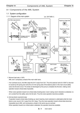
A-1 Components of the AML System 1.1 System configuration 1.1.1 Diagram of the main system
(ex. GR-700N-1)
1. Moment load ratio ≥ 100% AML vent / compulsory unload of the main relief valve. ۰ If an overload occurs, the AML stops the 24-V output from Do1. Thus the solenoid valve for VENT is returned to neutral by the spring and vents the oil in the spring side of the balance piston in the main-circuit safety valve into the tank circuit. The whole oil discharged by the pump is unloaded into the tank, making crane operation toward critical sides impossible. ۰ When crane operation toward non-critical sides (hoisting down, boom raising, boom retraction) is detected, no oil is vented from the safety valve into the tank. Thus the crane operation becomes available. 2. Anti-two-block (overwind) stop: If operation toward critical sides (hoisting up, boom lowering, boom extension) is attempted while the hook block is over wound, 24-V output from Do1 stops. Thus the crane operation toward critical sides becomes impossible due to AML vent (compulsory unload) in the same way as overload. When operation toward non-critical sides is detected, the operation becomes available.
A-1
W301-0481E


