2 minute read
Adjustment mode


D-3 Moment / Load Radius Adjustment
Perform the moment adjustment / load radius adjustment according to the description below.
Advertisement
- Select the moment adjustment of Adjustment main menu
- Moment zero adjustment
- Moment span preliminary adjustment / load radius adjustment
- Moment span adjustment
- Moment zero check
Measurement condition:
1. Perform all the adjustments with the outrigger become fully extended.
2. The number of part-lines shall be the standard number of part-lines for boom full extension.
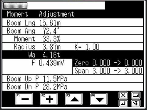
When "Moment Adjustment" is selected in the adjustment main menu of Fig. 1.3.3, the detector adjustment screen appears on the LCD as shown in Fig. 3.1.1.
K: Deflection coefficient adjustment multiplication
Wa: Actual load
F: Distortion voltage (converted from elevate cylinder’s both side pressure)
Zero: Input distortion at zero adjustment
→ Distortion voltage to be corrected
Span: Input distortion at span adjustment
→ Distortion voltage to be corrected
[NOTICE]
With the moment adjustment, be sure to set the boom angle by the boom lowering operation, and always wait until the distortion voltage becomes stable before starting the adjustment. Under the moment adjustment status, pressing the check < > key performs the compulsory unload output. During compulsory unload output, the buzzer of display control section is sounded intermittently with a long duration to notify that the compulsory unload output is in progress. During this period, the distortion voltage can be stabilized quickly when the boom lowering operation is performed. When the check < > key is pressed again, the status returns to the normal control.
3.1 Moment Zero Adjustment
1. Fully retract the boom, and lower the boom to the specified boom angle.
2. With no load (Main hook block only), set the hook to the two-blocking status.
3. In the LCD (Fig. 3.1.1), press the < > key (backward) or the < > key (forward) until both of "Wa" and "Zero" become highlighted.
Wa: Actual load F: Distortion voltage (converted from an elevating cylinder’s both side pressure)
4. Operate the < > key (-) and the < > key (+) so that the displayed actual load (Wa) becomes the adjustment value (The distortion voltage to be corrected changes.) When the actual load (Wa) becomes the adjustment value, press the < > key to register the adjustment value.
3.2 Moment Span Preliminary / Load Radius Adjustment
1. Fully extend the boom. Lift the rated lifting capacity (Max. Hook load) for boom full extension, and lower the boom to set to the maximum load radius for the lifted load.
2. In the LCD (Fig. 3.1.1), press the < > key (backward) or the < > key (forward) until both of "Wa" and "Span" become highlighted.
3. Operate the < > key (-) and the < > key (+) so that the displayed moment becomes to 100.0±1.0% (changes the distortion voltage to be corrected).
4. In the LCD (Fig. 3.1.1), press the < > key (backward) or the < > key (forward) until "Radius, K=" becomes highlighted.
Radius 6.78 m K=1.00
Load radius Deflection coefficient adjustment multiplication
5. Operate the < > key (-) and the < > key (+) so that the displayed load radius becomes the adjustment value. (The deflection coefficient adjustment multiplication changes.)
When the load radius becomes the adjustment value, press the < > key to register the adjustment value.
3.3 Moment Span Adjustment
1. Fully extend the boom, and lower the boom to the specified boom angle.
2. With no load (hook block only), hoist-down the hook block until just before touching the ground.
3. In the LCD (Fig. 3.1.1), press the < > key (backward) or the < > key (forward) until both of "Wa" and "Span" become highlighted.
Input distortion at span adjustment
Distortion voltage to be corrected
4 Operate the < > key (-) and the < > key (+) so that the displayed actual load Wa becomes the adjustment value (distortion voltage to be corrected).
When the actual load (Wa) becomes the adjustment value, press the < > key to register the adjustment value
3.4 Moment Adjustment Check
1. Set to the zero adjustment condition again (Refer to 3.1)
2. The adjustment is completed when the actual load is within the standard tolerance