Maintenance Mode
Cha pte r C
Cha pte r C
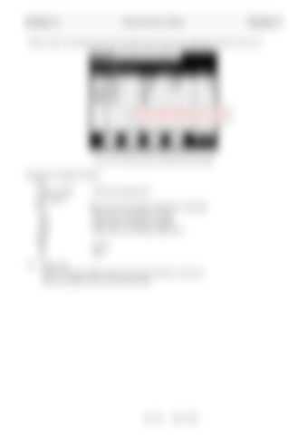
When a node is connected to the CAN, the state of each node is also displayed as shown in Fig. 2.5.2.
(The items differ depending on the model.)
Fig. 2.5.2 Si check screen including CAN node state <Description of display contents> Port CAN1 to CAN2
: CAN communication port
Signal Name ICF
: Node name of Information Controller for Telematics
VCU
: Node name of controller for Vehicle
DCU
: Node name of controller for Display
CMA
: Node name of Combination Meter Assy
State OK
: Normal
NG
: Error
N.L.: Noise Level Value for the data reception failure count (since the power is turned on). Used as a guideline of the communication state.
C - 11
W301-0481E


