Model 4700 Maintenance Manual
Section 7. Component Procedures
Drive and Brake Check Brake Disc Wear
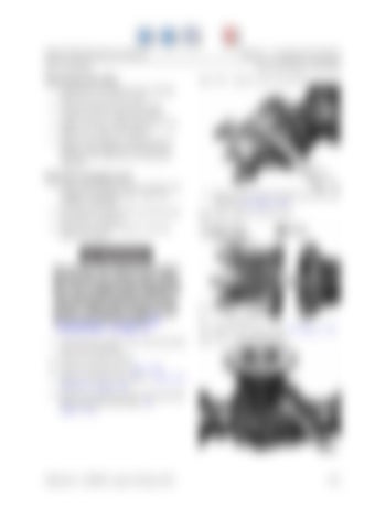
Drive Unit/Motor Assemblies Figure 7-28.
Reduction Gear Mounting Bolts
1. Disconnect the cable from the parking brake lever on the drive unit. 2. Actuate brake lever by hand until resistance is felt. Mark the position. 3. Apply a 370 ft. lb. (500 Nm) force to the brake lever. Mark the position. 4. Measure the distance between the two marks. If the distance exceeds 0.5 in. (13 mm), the brake disc set should be replaced. Brake Disc Set Replacement 1. Park the lift truck on a level surface and engage the parking brake. Lower the carriage completely. 2. Turn the key switch OFF and disconnect the battery connector.
9. Remove both reduction gears from the axle housing. See Figure 7-29. Figure 7-29.
Reduction Gear Removal
3. Block the steerable wheels to prevent truck movement.
Use extreme care whenever the truck is jacked up for any reason. Never block the truck between the telescopic and the floor. Use a suitable hoist to stabilize the mast. Keep hands and feet clear from beneath vehicle while jacking. Use jack stands or solid blocks to support truck. Do not rely on the jack alone. See “Jacking Safety” on page 2-8. 4. Jack the front of the truck. Securely block the truck in position.
10. Remove the flange bolts. See Figure 7-30. Figure 7-30.
Flange Mounting Bolts
5. Remove the drive wheels. 6. Drain the fluid (refer to page 7-27). 7. Remove the drive unit. Refer to “Drive Unit Removal” on page 7-28. 8. Remove the reduction gear mounting bolts from both sides of the axle. See Figure 7-28.
Publication 1160093, Issued: 20 May 2013
7-31


