2 minute read
Model 4700 Maintenance Manual
Drive
Section 7.Component Procedures
and Brake Drive Unit/Motor Assemblies
Single Traction Motor Trucks
The drive unit/motor assembly consists of a planetary gear type drive unit and an AC motor.
Drive units on trucks below S/N 10677 have a automotive type shoe brake. See “Brake Service - S/Ns below 10677” on page7-29. Drive units on trucks S/N 10677 and up have a internal wet-brake system. See “Brake Service - S/Ns 10677 and up” on page7-30.

Changing Fluid
S/Ns below 10677
1.Run the truck for a few minutes to warm the fluid.
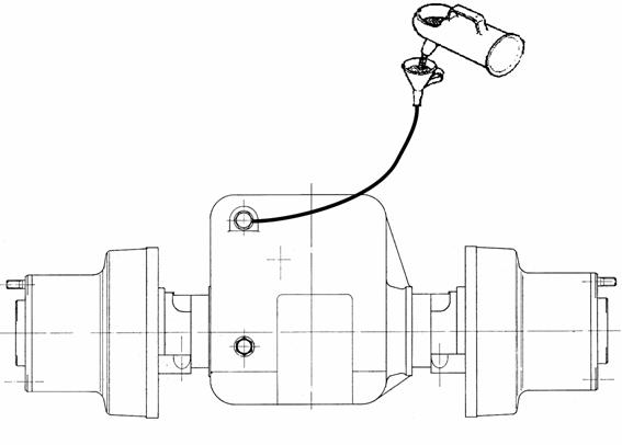
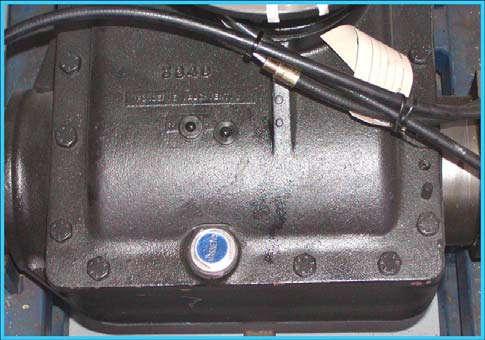
2.Clean the area around the fill and drain plugs. See Figure7-22.
4.Remove both the fill and drain plugs. Allow fluid to drain out completely.
5.Clean any ferrous residue from the magnetic drain plug. Replace the drain plug.
6.Use a flexible hose with either a syringe or a funnel to add new fluid through the fill plug hole until it is visible halfway up the level window (approx. 2.6 qt./2.5 liter). Refer to "Lubrication Specification Chart" on page A-2 . Install the fill plug.
7.Clean the area around the fill and drain plugs.
8.Run the truck for several minutes. Check fluid level again. Add fluid as necessary.
S/Ns 10677 and up
NOTE : S/N trucks 10677 and up require a specific break-in oil (P/N 990-603/SPL) for the first 1500 hours of operation.
1.Run the truck for a few minutes to warm the fluid.
2.Clean the area around the oil fill/oil level plug and drain plugs. See Figure7-23.
3.Remove the oil fill/oil level plug. Remove the sealing ring from the plug.
4.Place suitable container(s) below the drain plugs.

5.Remove the drain plugs. Remove the sealing rings from the plugs. Allow fluid to drain out completely.
6.Clean any ferrous residue from the magnetic drain plugs. Install the drain plugs with new sealing rings.
Publication 1160093, Issued: 20 May 2013
Section 7.Component Procedures
Model 4700 Maintenance Manual
Drive Unit/Motor Assemblies Drive and Brake
7.Use a flexible hose with either a syringe or a funnel to add new fluid through the fill hole until the oil level is at the bottom edge of the fill hole/(approx. 1 gal./4 liters). Refer to "Lubrication Specification Chart" on page A-2 . Install the fill plug with new sealing rings.
8.Clean the area around the oil fill/oil level plug and drain plugs.
9.Run the truck for several minutes. Check fluid level again. Add fluid as necessary.
Drive Unit Removal
1.Remove mast. See “Mast Removal and Installation” on page7-68.
2.Block the steerable wheels to prevent truck movement.
Use extreme care whenever the truck is jacked up for any reason. Never block the truck between the telescopic and the floor. Use a suitable hoist to stabilize the mast. Keep hands and feet clear from beneath vehicle while jacking. Use jack stands or solid blocks to support truck. Do not rely on the jack alone. See “Jacking Safety” on page2-8.
3.Jack the front of the truck. Securely block the truck in position.
4.Remove and cap the hydraulic brake line(s).
5.Remove the floor plate from the operator compartment.
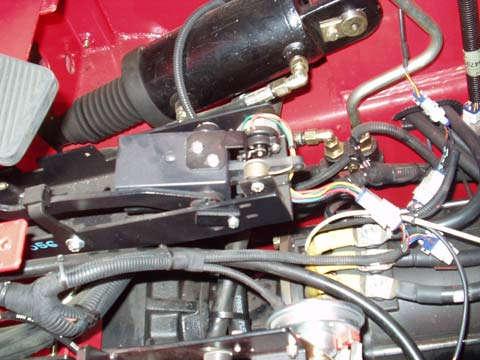
6.Disconnect the accelerator pot connector and remove the accelerator pedal assembly. See Figure7-24.
7.Remove the upper and lower covers from the parking brake cable assembly.

8.Disconnect the parking brake cable.
9.Secure the drive unit using suitable hoist straps placed around the flared flange attaching the drive unit to the traction motor.
10.Block the front of the traction motor.
11.Remove the four bolts securing the traction motor to the drive unit. Separate the drive unit from the traction motor.
NOTE : On drive units with automotive type shoe brakes, make sure the bolts are removed from the large flared end of the flange (closest to the traction motor). Do not remove the six bolts on the small end of the flange (closest to the drive unit).
12.Remove hardware securing the drive unit to the chassis.
13.Using a hoist, carefully roll drive unit assembly forward and away from the chassis.
Drive Unit Installation
1.Secure the drive unit using suitable hoist straps placed around the flared flange of the drive unit.
2.Carefully assemble the drive unit to the traction motor. Make sure the pinion and spur gears mesh correctly.
Publication 1160093, Issued: 20 May 2013


