3 minute read
Model 4700 Maintenance Manual
Quad Mast Cylinder Service
Main or Free Lift Cylinders
1.Remove the cylinder from the mast. See “Cylinder Removal and Installation” on page7-84.
2.Use a claw-type spanner wrench to remove the retainer from the shell.
3.Remove the plunger/piston assembly from the shell.
4.Inspect all components for nicks or burrs. Minor nicks or burrs can be removed with 400-grit emery cloth.
NOTE : Minor nicks are those that will not bypass oil when unde r pressure. If they cannot be removed with emery cloth, replace the part. If the piston requires replacement, refer to “Piston Removal”
5.Replace the retainer and piston seals, back-up rings, O-rings, and bearing. Lubricate the new seals with petroleum jelly prior to installation. Note correct seal direction. The seal lip always points toward the pressure side of cylinder. The cylinder will not operate correctly if the seals are installed backwards.
6. Main Lift Cylinder - Install the plunger retainer on the plunger. Install the plunger/piston assembly into the cylinder shell. Using the claw spanner and strap wrenches, tighten the retainer to 95 to 125ft. lb. (129 to 169Nm).
Free Lift Cylinder - Install the plunger retainer on the plunger. Install the plunger/piston assembly into the cylinder shell. Pour 1/2 cup (120 ml) hydraulic oil into the cylinder cavity between the shell and rod. Using the claw spanner and strap wrenches, tighten the retainer to 95 to 125ft. lb. (129 to 169Nm).
Piston Removal
1.Remove the plunger/piston assembly from the cylinder shell.
Section 7.Component Procedures
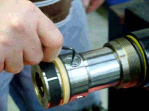
2.Use a strap wrench and 400-grit emery cloth to secure the plunger while turning the piston with a pin type spanner wrench. See Figure7-78. Figure 7-78.Piston Removal
3.Turn the piston until the snap wire end is visible through the hole. Use a screwdriver to start the wire end out the hole. Turn the piston to feed the wire out.
4.Pull the piston from the plunger.
5.For reassembly, reverse the removal procedure. Install a new snap wire when installing the piston.
Check Valve Inspection
Some Quad masts may experience drift if the check valve(s) in the right side main lift cylinder become loose.
1.Remove the right side main lift cylinder.
2.Remove piston.
3.Remove check valve. See Figure7-79. Figure 7-79.Quad
Section 7.Component Procedures
Quad Mast Cylinder Service
4.Inspect check valve. If the O-ring is missing or damaged, replace the check valve. Refer to Parts Manual.
5.Clean check valve and apply thread-locking compound (P/N 990-403) to circumference of check valve.
6.Re-install check valve and torque to 50in.lb. (5.65 Nm).
7.Repeat steps 3 thru 6 for remaining two check valves.
8.Reassemble cylinder and install in mast.
Valve Cartridge Replacement
1.Lower mast completely.
2.Remove supply hose from the valve cartridge. Plug the hose. See Figure7-80.
Figure 7-80.Valve Ca rtridge Replacement
Replacing the valve cartridge with a different part number may cause the mast to malfunction.
4.Install new valve cartridge.
5.Connect supply hose.
Valve Cartridge
Supply Hose
3.Remove the valve cartridge from the lowering control valve. Note the stamped part number on the cartridge when ordering a replacement.
Publication 1160093, Issued: 20 May 2013
Section 7.Component Procedures
Model 4700 Maintenance Manual
Mast Removal and Installation Mast
Mast Removal and Installation
Dual Traction Motor Trucks
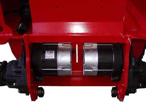
The base of the mast is attached to the tractor frame near the traction motors and to the tilt cylinders.

Removal
1.Park the lift truck on a level surface and engage the parking brake. Lower the carriage completely.
2.Tilt the mast completely forward.
3.Turn the key switch OFF and disconnect the battery connector.
4.Block the steerable wheels to prevent truck movement.
5.Remove forks.
6.Double wrap a sling around the top of the mast. Attach a suitable lifting device to the mast and lift until the sling is snug.
7.Remove the lower bearing caps and bolts clamping the base of the mast to the chassis. See Figure7-81.
9.Disconnect the main hydraulic hose at the base of the mast.
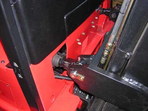
10.Remove the screws, lock washers, and plate securing the pins through the tilt cylinder yoke and mast mounting brackets. Remove the cylinder mounting pins. See Figure7-82.
Mounting Points
NOTE : The bearing caps are machined. Mark each bearing cap so that it is returned to the correct side during mast installation.
8.Disconnect the auxiliary supply hoses at the sides of the mast.
7-68
11.Lift the mast away from the lift truck slowly until you have enough room to reach the bleeder hose. Disconnect the bleeder hose, then continue moving the mast away from the lift truck.
12.Slowly lower the mast until it lays flat on the floor.
Installation
1.Double wrap a sling around the top of the mast. Attach a suitable lifting device to the mast and slowly lift the mast to vertical.
2.Slowly move the mast toward the lift truck, aligning the mast mounts.
3.Before the mast is fully in position, connect the bleeder hose to the reservoir.
4.Finish aligning the mast on the mast mounts.
5.Place the pins through the tilt cylinder yoke and mast mounting brackets.

NOTE : Make sure the bearing caps are returned to the correct side during mast installation.
6.Install the lower bearing caps and bolts securing the base of the mast to the
Publication 1160093, Issued: 20 May 2013


