1 minute read
Model 4700 Maintenance Manual
Section 7.Component Procedures
Drive and Brake Drive Unit/Motor Assemblies
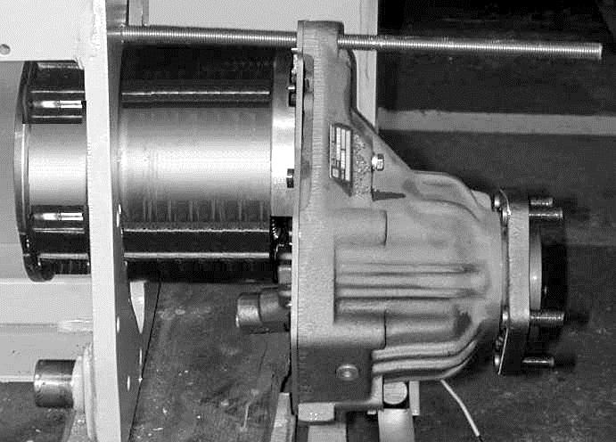
8.Remove the drive unit/motor assembly from the tractor as follows: a.Remove the upper front drive unit mounting bolt and install an M14x30 threaded rod as shown in Figure7-16 to support the drive unit/motor assembly.
Drive Unit Installation
1.Carefully assemble the drive unit to the traction motor. Make sure the pinion and spur gears mesh correctly.
2.Torque the motor to drive unit mounting bolts to 17 ft. lb. (23 Nm).
3.Install the drive unit/motor assembly into the chassis in the reverse of removal.
4.Torque the drive unit to chassis mounting bolts to 100 ft. lb. (135 Nm).
b.Remove the remaining five mounting bolts. Slide the drive unit/motor assembly out of the chassis.
c.If the traction motor is to be removed from the drive unit, remove the three bolts attaching the drive unit to the motor. See Figure7-17.
Traction Motor Mounting Bolts
When separating the motor from the drive unit, do not damage the gears or O-ring sealing surface in the housing.
Cover the opening of the drive unit to prevent contamination while the motor is removed.
Publication 1160093, Issued: 20 May 2013 7-23
Section 7.Component Procedures
NOTE : Replace the brake disk sets in both drive units at the same time.
Drive
Publication 1160093, Issued: 20 May 2013


