1 minute read
Model 4700 Maintenance Manual
Wiring
Visually inspect all wiring and electrical components for:
•Loose connections or connectors
•Loose or broken terminals
•Damaged terminals, blocks, or strips
•Exposed wire at terminations, excessive strip gap
•Abrasions, scrapes, nicks in the wire, damage from overheating or burns, or other general insulation damage
•Broken wire strands and shorte d co nditions (especially those that are clo se to metal edges or surfaces)
During troubleshooting and repairs, it may be necessary to unplug a connector, move a harness, cut a cable tie, or remove the wire from a bracket. Note the location of the wire and all protective or securing attachments before moving the harness.
After repair, return or replace all protective and/or securing hardware to its original condition. Protective materials are necessary to provide reliable performance of the interconnect system.
Examine and maintain any added materials used to dress and protect the wire. This includes spiral wrap, brackets, cable ties, fasteners, and flexible conduit.
Do not attach cable ties so tight that they pinch cable harnesses. Avoid attaching cables to hydraulic hoses that expand with pressure, pinching the attached electrical cables.
Use a DMM to check for wiring continuity.
Electrical Connections
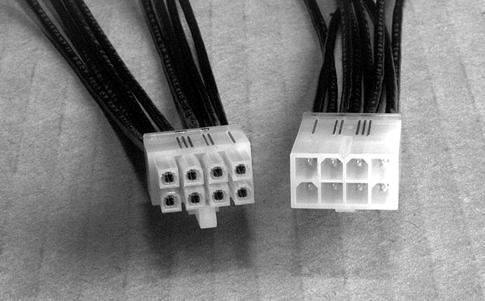
Molex connectors have ridges on the sides to help locate pin number 1. The short side has a single ridge at pin number 1. The long side has 1, 2, and 3 raised ridges at pin numbers 1, 2, and 3. See Figure5-2.
Publication 1160093, Issued: 20 May 2013
Section 5.Troubleshooting Electrical Troubleshooting
Pin Identifier Lines (black lines added for clarity)
Section 5.Troubleshooting
Model 4700 Maintenance Manual
Connector Locator Tables
Table 5-2.Connector Chart
* = Dual Traction Motor Trucks
** = Single Traction Motor Trucks S/N <10677
*** = Single Traction Motor Trucks S/N >10676
Connector Truck Location Function/Destination
JAMHCB(Not Used)
JAPPump Power Amplifier *(Not Used)
JATTraction Power Amplifier *CAN-Bus Connector for TPA
***Connector for C60 and EE Configuration
JBPPump Power Amplifier *Pump Motor Configuration jumper
***Main Connector for PPA
JBTTraction Power Amplifier *(Not Used) ***(Not Used)
JCMHCB Connector for Solenoids from HCB
JCPPump Power Amplifier
JCTTraction Power Amplifier
JDPPump
Electrical Troubleshooting 5-8
CAN-Bus Connector for PPA ***CAN-Bus Connector for PPA
Main Connector for TPA ***CAN-Bus Connector for PPA
Publication 1160093, Issued: 20 May 2013


