1 minute read
Model 4700 Maintenance Manual
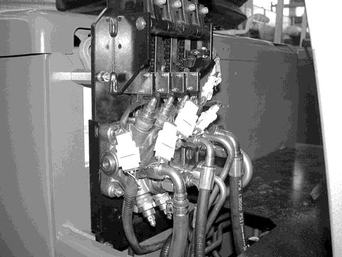
Section 7.Component Procedures
Electrical Components Potentiometers
3.Plug the wiring harness connectors into the travel pot and switch(es).
4.Run Learn for the travel pot in FlashWare.
Lift Potentiometer (P3)
Removal
1.Turn the key switch OFF and disconnect the battery connector.
2.Remove the control valve cover.
3.Unplug the wiring harness connector to the lift pot.
4.Loosen the socket head screw securing the clamp on the lift pot shaft.
5.Remove the hardware securing the lift pot to the bracket.
6.Remove the pot from the bracket.
1.Place the lift pot shaft through the hole in the control valve bracket. Align the locator pin with the hole in the mounting plate.
2.Install the lock washer, nut, and washer ring on the lift pot shaft. If the articulated joint is broken and/or the pot shaft slips in the articulated joint bracket, replace the articulated joint.
3.Tighten the socket head screw in the shaft clamp. Operate the lift/lower lever and check for misalignment. The pot is sensitive to axial and side loading. If the shafts or pot mounting brackets are misaligned, repair or replace. If there is excessive axial clearance, add a washer on the pivot shaft to reduce the axial movement.
4.Verify resistance decreases linearly when the lift lever is pulled.
5.Verify the lift microswitch operates correctly.
6.Run Learn for the lift pot in FlashWare. Lift Pot
Installation
Before installing the new pot, connect a DVM (set to resistance and 20,000 ohm range) between the green and yellow wires on the pot assembly. While rotating the pot shaft for one full rotation, monitor the resistance of the pot. There are two positions where the resistance varies between 0 and approx. 5,000 ohms. These positions are approx. 180 ° of shaft rotation from each other. One location uses approx. 20 ° of pot rotation and the other uses less than 10 ° of rotation. Position the shaft in the 20° location before installing pot.
Publication 1160093, Issued: 20 May 2013 7-53
Section 7.Component Procedures
Model 4700 Maintenance Manual
Motor Encoder Bearing Electrical Components


